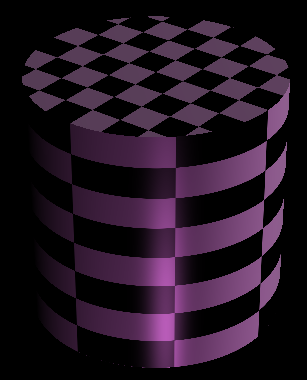
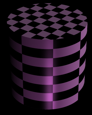
Project 3: Intersect
When cloning the stencil code for this assignment, be sure to clone submodules. You can do this by running
git clone --recurse-submodules <repo-url>
Or, if you have already cloned the repo, you can run
git submodule update --init --recursive
You can find the algo for this project here.
Introduction
In this assignment, you will implement the first (and most fundamental) part of a ray tracer: a pipeline for shooting rays into a scene and checking what (if anything) they hit.
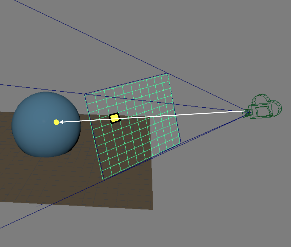
The following diagram shows an example of one ray shooting through a pixel on the viewplane and intersecting with a sphere in the scene. Your goal in this assignment is to implement a system that does this with any given input scene data.
Requirements
Parsing The Scene
You will use the same scenefiles from the Parsing lab to describe a scene. For your ray tracer, you will load the scene from a scene file, parse it, and then render the scene with the ray tracing algorithm. Hence, you first need to correctly parse the scene. Please make sure you finish the parsing lab first before starting on this project.
Refer to section 3.1 on where in the codebase to implement the parser.
Generating And Casting Rays
To generate and cast rays into the scene, you will need to shoot rays through a pixel on the viewplane. For basic requirements, you are only required to shoot one ray through the center of each pixel.
Finding Intersection Points
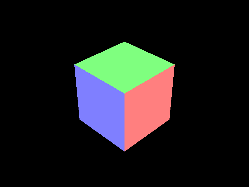
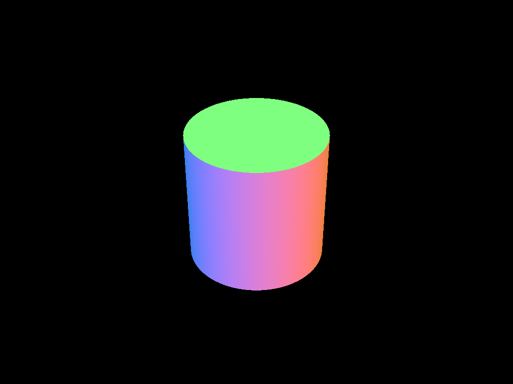
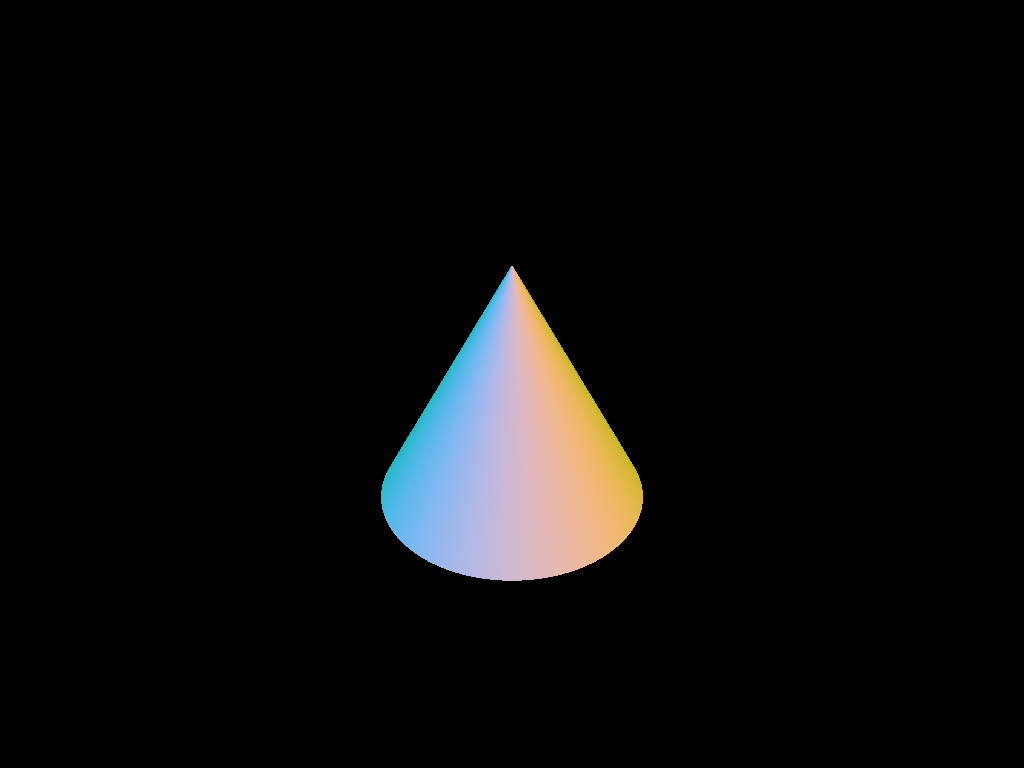
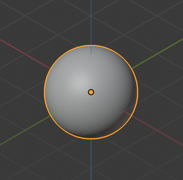
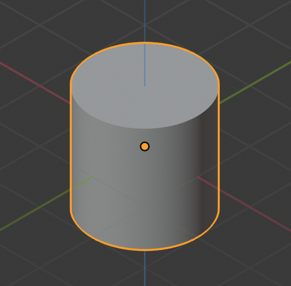
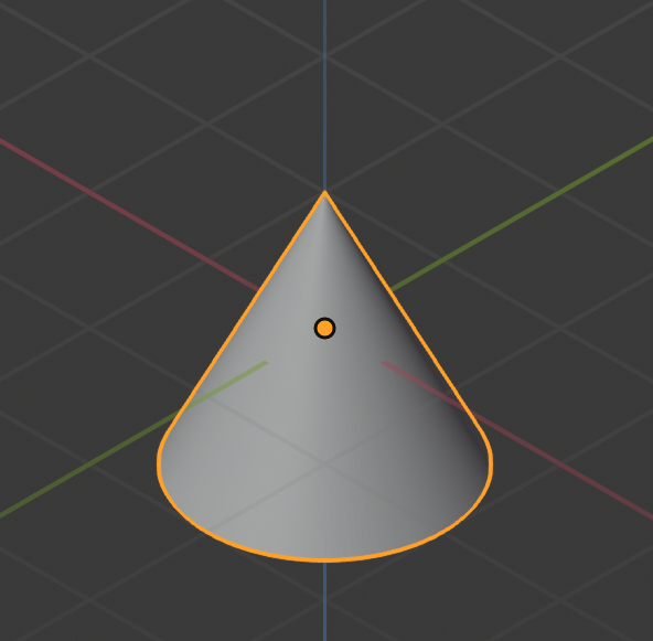
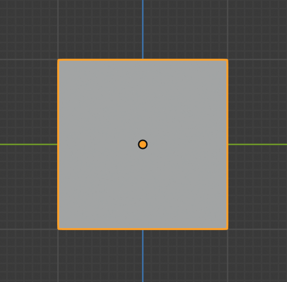
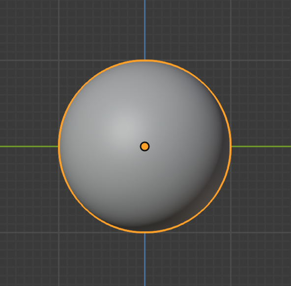
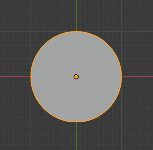
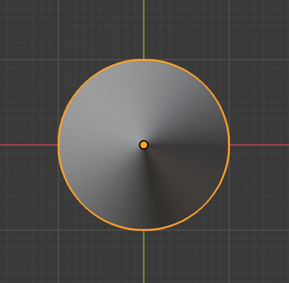
In order to find an intersection point, we first have to define our shapes. As covered in lectures, we are going to use implicit functions to define our shapes. You are required to be able to correctly handle four (4) types of implicit shapes.
Cube | Sphere | Cylinder | Cone |
|---|---|---|---|
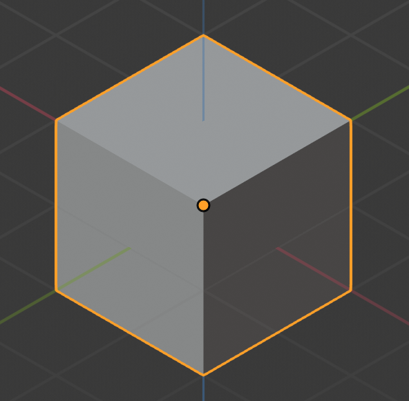 |  |  |  |
 |  |  |  |
Symmetry | Symmetry | 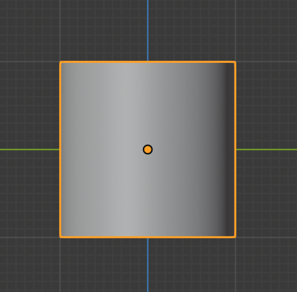 | 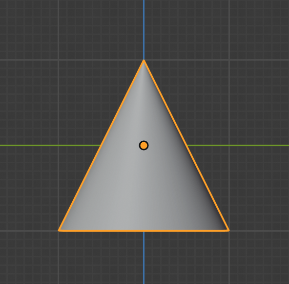 |
All shapes are fit within a bounding box with side length 1 centered about the origin,
- Cube: A unit cube (i.e. sides of length 1) centered at the origin
- Cone: A cone centered at the origin with height 1 whose bottom cap has radius 0.5
- Cylinder: A cylinder centered at the origin with height 1 whose top and bottom caps have radius 0.5
- Sphere: A sphere centered at the origin with radius 0.5
Remember that we have the following 3 different spaces to work with. Please think thoroughly which step should happen in what space, and how to transform among them, before actually start writing your code.
- World space
- Camera space
- Object space
Lighting
If you haven't finished Lab 6: Light, please go finish it before making further progress. It will walk you through Phong illumination model with point light.
However, for this assignment, you are only required to implement the Phong illumination model with directional light. You will handle other types of light sources in the next assignment.
You are certainly welcome to push yourself further and implement point light ahead of schedule, because that's already covered in Lab 6.
However, please make sure that your submission for Project 3: Intersect does not contain support for point light, because your image output may look different with both point light and directional light support.
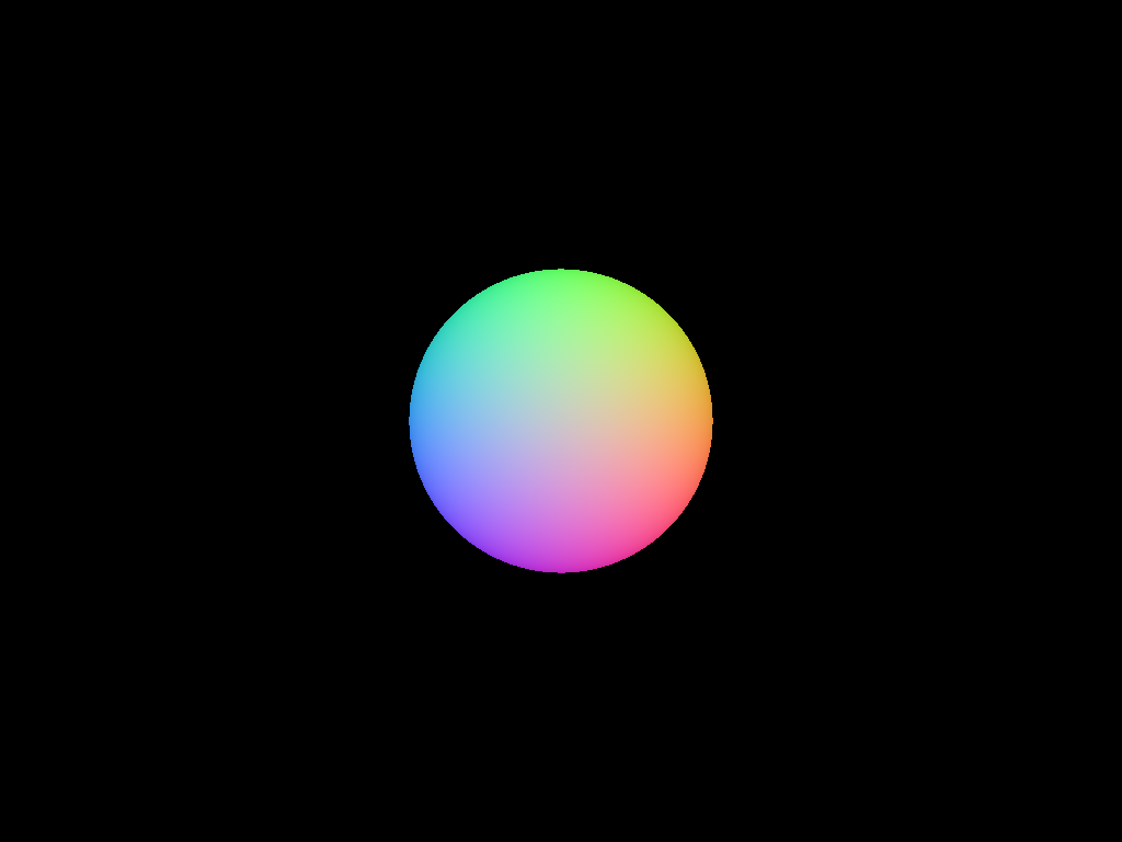
Regardless of whether or not you've done the lab a helpful step is to use the normals as the object color. This will allow you to verify that your normals are correct before implementing Phong Illumination. The equation we use for normal-to-color mapping in the solution is color = (normal + 1) / 2 where the components of the normal correspond to the red, green, and blue channels of the color respectively. Rendering normals in that way produces the following images:
Unit primitives rendered with their normals as their colors. Based on unit_cube.json, unit_cylinder.json, unit_cone.json, and unit_sphere.json.
You can run the demo (see the TA Demos section) with only-render-normals = true in the QSettings.ini file to produce more expected outputs like this.
The Phong illumination model is one of many lighting models to simulate the reflectance of light striking a surface. It computes the overall lighting as the combination of three components: ambient, diffuse, and specular.
Click here for a full breakdown of the equation's terms.
| Subscript | What It Represents |
|---|---|
| A given wavelength (either red, green, or blue). | |
| A given component of the Phong illumination model (either ambient, diffuse, or specular). | |
| A given light source, one of |
| Symbol | What It Represents |
|---|---|
| The intensity of light. E.g. | |
| A model parameter used to tweak the relative weights of the Phong lighting model's three terms. E.g. | |
| A material property, which you can think of as the material's "amount of color" for a given illumination component. E.g. | |
| The total number of light sources in the scene. | |
| The surface normal at the point of intersection. | |
| The normalized direction from the intersection point to light | |
| The reflected light of | |
| The normalized direction from the intersection point to the camera. | |
| A different material property. This one's called the specular exponent or shininess, and a surface with a higher shininess value will have a narrower specular highlight, i.e. a light reflected on its surface will appear more focused. | |
| The attenuation factor. You can ignore this for the scope of this assignment. |
For this assignment, since you are only working with directional lights, do not implement the attenuation effects described in this equation.
Results
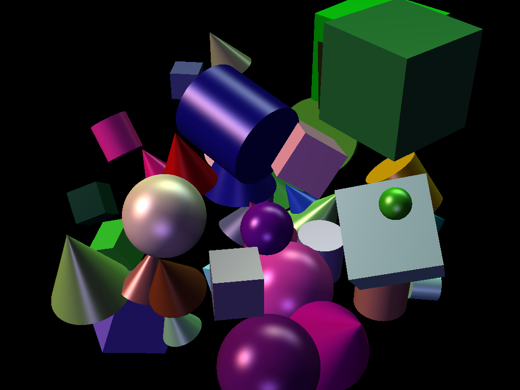
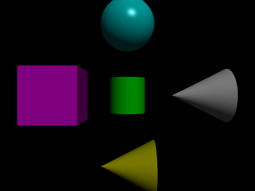
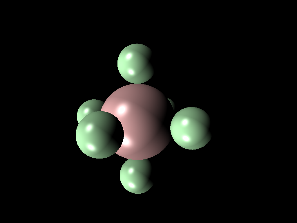
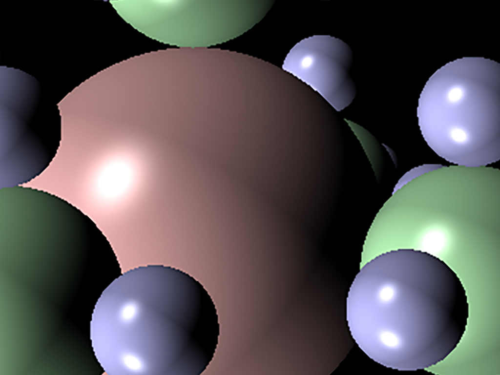
Here are some sample images of what your ray tracer should be capable to render by the end of this assignment.
Left: primitive_salad_1.json; Middle: phong_total.json; Right: recursive_sphere_2.json
Stencil Code
Codebase
For this assignment and the next one, you are going to use a command line interface rather than a GUI. Your program, when run from the command line, will read from a config file and a scene file, parse those files, render a scene to an image, and then write that file to disk. The stencil code we have provided you already takes care of reading from the config file and the scene file and parsing the config file into parameters.
This config file is called QSettings.ini. Here is a sample config file for reference. You can take a look at main.cpp to figure out how the config file is parsed.
The codebase is structured with three modules.
-
The
utilsmodule provides the utilities you will use for the ray tracer.- You should implement the
SceneParseras you have done similarly in the parsing lab.
- You should implement the
-
The
cameramodule contains everything related to camera operation.- You must implement the camera for your ray tracer.
Camera.hdefines a suggested interface for the camera, but it is not required that you conform to this.
-
The
raytracermodule is the main component of this assignment. You will write the majority of your code here.- In
RayTraceScene, you will construct the scene using theRenderDatayou filled in theSceneParser - In
RayTracer, you will implement the ray tracing algorithm. It takes in aRayTracer::Configduring initialization. RayTracer::Configis a struct that contains various flags to enable or disable certain features.
- In
You have the freedom to add any class you think that is necessary for this assignment. But please do keep the existing interface intact, because the TAs are relying on the interface to grade your assignment.
You may notice that the stencil already has some existing config parameters. Some of them are for the next assignment, others are for optional extra credit features. However, if you feel like implementing an extra feature that is not included in the existing config parameters, feel free to add the new parameter to your .ini file and the RayTracer::Config. If you do this, you should also document this change in your README to help TAs with grading.
Scene Files
We provide a large set of scenefiles which you can use as input to your ray tracer in this Github repo.
For this assignment, you will be required to include your raytracer's output for all scenefiles inside of intersect/required in your README. There are also
more scenefiles you can use inside of intersect/optional, although these are optional (as the name implies) and just for fun/additional testing if you'd like.
Expected outputs for these scenefiles are located inside of intersect/required_outputs and intersect/optional_outputs respectively.
Although there are a vast number of other scenefiles inside the repo, many of them are not yet supported by your ray tracer, since you are only required to implement directional light and that's ok!
We only expect you to be able to correctly render the scenefiles in the required folder mentioned above for this assignment. You will unlock your ray tracer's full capability in the next assignment yourself!
Design
Keep in mind that in this assignment, you are only implementing the first of your ray tracer, and you will keep working with the same code repo for the next assignment.
When making your design choices, think a bit further about what could be needed in the next assignment, and whether your design provides the flexibility for you to easily extend its features. The next assignment will require you to implement different light sources, texture mapping, shadows, and reflections.
This is probably the first assignment in the course where you might find yourself wanting to use runtime polymorphism to organize your code (e.g. a Primitive abstract type that can be a Sphere or a Cone, etc.).
C++ provides a couple of ways to achieve this common object-oriented design pattern; check out the runtime polymorphism section of the Advanced C++ Tutorial to learn more.
Running Your Code
As mentioned in the codebase section earlier, to run your program, you will need to create a .ini file containing the raytracing parameters, an absolute filepath to the scenefile, and an absolute filepath to the output image.
Note that all filepaths within Qt and the .ini file should be written using forward slashes (/). This is the default filepath separator on macOS and Linux, but not always(?) on Windows.
By the way, you can create your .ini file anywhere on your disk, as you will be passing its absolute filepath as a command line argument to your program.
Scenes Viewer
To assist with creating and modifying scene files, we have made a web viewer called Scenes. From this site, you are able to upload scenefiles or start from a template, modify properties, then download the scene JSON to render with your raytracer.
We hope that this is a fun and helpful tool as you implement the rest of the projects in the course which all use this scenefile format!
For more information, here is our published documentation for the JSON scenefile format and a tutorial for using Scenes.
TA Demos
Demos of the TA solution are available in this Google Drive folder. projects_intersect_min is the "minimum" solution with the baseline requirements complete. projects_intersect_max is the "maximum" solution with all of the extra credit features implemented.
macOS Warning: "____ cannot be opened because the developer cannot be verified."
If you see this warning, don't eject the disk image. You can allow the application to be opened from your system settings:
Settings > Privacy & Security > Security > "____ was blocked from use because it is not from an identified developer." > Click "Allow Anyway"
Instructions for Running
You can run the app from the command line with the same .ini filepath argument that you would use in QtCreator. You must put the executable inside of your build folder for this project in order to load the scenefiles correctly.
On Mac:
open projects_intersect_<min/max>.app --args </absolute/filepath.ini>
On Windows and Linux:
./projects_intersect_<min/max> </absolute/filepath.ini>
Submission
Your repo should include a submission template file in Markdown format with the filename submission-intersect.md. Follow the instructions Output Comparison section of the template to populate the student output column. You should also list some basic information about your design choices, the names of students you collaborated with, any known bugs, and the extra credit you've implemented.
For extra credit, please describe what you've done and point out the related part of your code. If you implement any extra features that requires you to add a parameter for QSettings.ini and RayTracer::Config, please also document it accordingly so that the TAs won't miss anything when grading your assignment.
Grading
This assignment is out of 100 points:
- Scene parsing (10 points)
- Camera (10 points)
- Phong (28 points)
- Ray-primitive intersections (32 points)
- Software engineering, efficiency, & stability (20 points)
Remember that filling out the submission-intersect.md template is critical for grading. You will be penalized if you do not fill it out.
Extra Credit
-
Acceleration data structure: There are many types of spatial data structures you could use to accelerate ray/object intersections. Here are the approaches that are covered in lecture:
- Octree (up to 7 points)
- BVH (up to 10 points)
- KD-Tree (up to 10 points)
A correctly implemented acceleration data structure should allow you to render every scene we have in the scenefile repo in seconds (even with a single thread).
By "render", it means that the time for constructing the data structure is excluded.
Your implementation are expected to achieve a similar performance level.
-
Parallelization: There are many ways to parallelize your code, ranging from a single-line OpenMP directive to a carefully-designed task scheduler. The amount of extra credit you receive will be based on the sophistication of your implementation. If you have more questions on the rubric or design choices, come to TA hours and we are happy to help.
- Level 1: OpenMP based (up to 1 point)
- Level 2: Qt based, simple implementation (up to 2 points)
- Level 3: Qt based, relative sophisticated implementation (up to 4 points)
- Level 4: Qt based, extensive implementation (up to 6 points)
-
Anti-aliasing (up to 3 points): If you only shoot one ray through the center of each pixel, you'll see jaggies (aliasing) due to undersampling of high-frequency parts of the scene (e.g. object edges). In the Filter unit, we discussed some ways to ameliorate (but not completely fix) aliasing with some post-processing. See if you can integrate your Filter code into your ray tracer as a post-processing module for your output image.
-
Super-sampling: As mentioned above, the source of aliasing is the low number of ray-per-pixel samples. The most direct way to resolve the problem is to increase the number of samples. Here are a few ways to do super-sampling:
- Naïve super-sampling (up to 3 points)
- Adaptive super-sampling (up to 6 points)
Figure 5: Left: one ray per pixel. Right: multiple rays per pixel Depending on your strategy, adaptive super-sampling can increase your computation cost exponetially, but don't worry, it is acceptable.
-
Create your own scene file (up to 3 points): Create your own scene by writing your own scenefile or by using Scenes. Refer to the provided scenefiles and to the scenefile documentation for examples/information on how these files are structured. Your scene should be interesting enough to be considered as extra credit (in other words, placing two cubes on top of each other is not interesting enough, but building a snowman with a face would be interesting).
-
Mesh rendering (up to 7 points): Implement a function to load an .OBJ triangle mesh file and render it with ray-triangle intersections. Note that if you choose to implement this feature, you will probably want to have an acceleration structure, too, as meshes with many triangles can be very slow to render otherwise. To receive credit for this feature, you should include at least one scene file that makes use of a mesh.
CS 1234/2230 students must attempt at least 14 points of extra credit, which must include an implementation of one acceleration data structure.
FAQ & Hints
Nothing Shows Up
- Use the QtCreator debugger to debug. Don't just run everything in Release mode!
- Start with a simple scene, such as a scene with only one primitive, and make sure it's working.
- Think thoroughly about the whole ray tracing pipeline before start writing your code.
- What are the transformations needed to compute the final output?
- Does the math make sense?
- Are there any negative values or extremely large values during the computation?
- Try rendering with normals as colors, skipping your implementation of the Phong lighting model. See the Lighting section for some more info about how the demo accomplishes this.
My Output Images Have "Jaggies"
You may notice that your outputs have "jaggies" on edges as in the image shown below. These are aliases due to the low (one sample per pixel) sampling rate, so don't worry! Check out the extra credit section if you are interested in exploring ways to resolve this issue.
My Output Images Have Weird Colored Spots
Check if you are clamping your color values between 0 to 255, and that you aren't inadvertently causing any overflows.
My Ray Tracer Runs Very Slowly :(
Since the time complexity of the naïve ray tracing algorithm is
But that's not the end of the world! Here are some tips for you at different stages of the project:
While you're still working on your project:
Modern CPUs should have enough horsepower to handle most of our scenes. Even so, you'll definitely want to be able to render your scenes super quickly to check for bugs and errors as you iterate on your code.
One thing you can do is to limit the resolution of your output image.
Our default rendering resolution is
In particular, you may want to avoid working with intersect/optional/recursive_sphere_5.xml and up until after you've already successfully rendered simpler scenefiles.
When you have finished the basic requirements and are looking for more:
As mentioned in the lecture, ray tracing is 'embarrassingly parallel,' so you can boost performance simply by making your ray tracer parallel. There are many ways to achieve this; please refer to the Extra Credit section above for more information.
It's worth noting that acceleration data structures also offer a significant performance boost. Again, consult the Extra Credit section.
Submission
Submit your GitHub repo and commit ID for this project to the "Project 3: Intersect (Code)" assignment on Gradescope.
