Lab 10: Shaders
Please put your answers to written questions in this lab, if any, in a Markdown file named README.md in your lab repo.
Introduction
Welcome to the Shaders Lab!
In lab 9, you used VBOs and VAOs to pass vertex data to the GPU in the form of vertex attributes. Now, it's time to learn how to use that data to actually render images. To do this, we'll be writing (and learning about) shaders.
Fundamentally, a shader is just a program that gets run on the GPU. Because they are inherently parallelizable, shaders allow us to efficiently apply coordinate transforms, compute Phong lighting, and even implement fancy post-processing effects. However, running things on the GPU does make data handling a little more complicated, as you'll soon find out.
Objectives
- Understand the differences between vertex and fragment shaders.
- Learn to pass inputs and outputs to and from shaders, and
- Write, compile and use your own Phong illumination shader using GLSL.
Shaders In OpenGL
There are two types of shaders you will be writing for this lab: vertex and fragment shaders.
Extra: other types of shaders
OpenGL also supports geometry shaders, tessellation shaders, and compute shaders. You won't be required to use these for any of your work in this course, though you are welcome to explore them in your final project.
Vertex Shaders
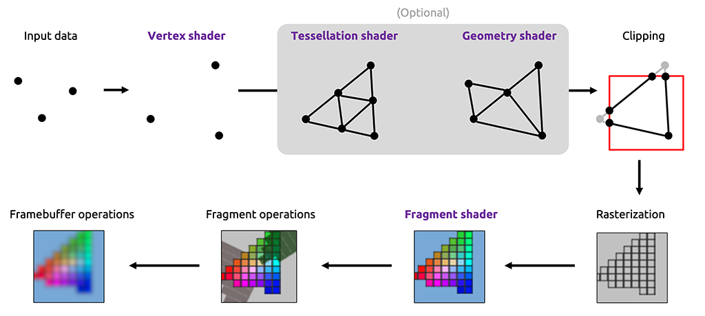
The vertex shader is the first shader run in the OpenGL pipeline. It acts directly on vertices (i.e. VAO/VBO data), so it's usually used to perform pre-processing transformations or other per-vertex computations.
The vertex shader is responsible for producing the final position of the vertex it acts on.
Fragment Shaders
On the other hand, the fragment shader is run much later in the pipeline. As its name implies, it acts on fragments.
The fragment shader is responsible for computing the final color of the fragment it acts on.
A fragment is a pixel-sized piece of a triangle. You can think of a fragment as a "potential pixel"—these fragments come out of the rasterization step, where triangles are broken down into fragments.
Extra: on the definition of a fragment
The definition we've provided above isn't the "whole truth", but it is sufficient for our purposes in CS 1230.
There are subtle differences between actual pixels and fragments. For instance, a fragment may be smaller than one pixel, if OpenGL is configured to do multisampling (i.e. produce multiple samples per pixel).
If you're interested to find out more, the responses to this StackOverflow question can be quite illuminating!
GLSL
Shaders are written in the OpenGL Shading Language (GLSL).
A set of shaders which implements the ones used in the OpenGL pipeline (minimally, a vertex shader linked with a fragment shader) is called a GLSL program.
In this lab, you will write a GLSL program which you will then use in your code—equivalently, you will write a vertex shader and a fragment shader. To get a quick overview of how to write GLSL, take a look at the dropdown below:
GLSL Syntax Speedrun
GLSL has syntax very similar to C. Common data types include:
float,int,boolvec2,vec3,vec4mat2,mat3,mat4
Also supported are:
- arrays using
[]syntax like C - structs
GLSL includes a number of helpful predefined functions, including:
sin,cos,tan, etc...pow,exp,log, etc...cross,dot,inverse,transpose
You can also write your own functions:
returnType functionName(argType argName, ... etc.) {
  // Your code here
}
Khronos provides an official "quick reference card" for GLSL. This is a dense(!) but complete listing of available types and functions in GLSL.
Getting Started
Stencil Code
In this lab, you will be working within the following files:
default.vert: the vertex shader,default.frag: the fragment shader, andglrenderer.cpp: specifically, two functions:initializeGL(), which prepares everything before rendering, andpaintGL(), which is called every frame to perform the actual rendering.
Much of the application has already been written for you. This includes:
generateSphereData(), a function which generates only position data for a sphere's vertices (recall that their normals can easily be computed as their normalized positions);- VAO- and VBO-related OpenGL calls needed to load the above data into the GPU; and
- A
ShaderLoaderclass, which you'll get to use shortly.
CPU-Side Code
Before we can get into writing actual GLSL, we must first scaffold our application on the CPU side.
Loading Shaders
First of all, you're going to want to be able to load, compile, and link the vertex and fragment shaders that you'll be writing.
This requires a sizeable amount of boilerplate code that doesn't have much pedagogical value. Thus, we've provided you with the ShaderLoader class, which implements a static method, createShaderProgram(), which you can use to handle this.
ShaderLoader::createShaderProgram() takes in the filepaths to the vertex and fragment shader and does all the preparatory work for you. The programID it returns can then be used with other OpenGL functions to activate and deactivate the shader for drawing (that said, this isn't as important in this lab, as we only have one shader program).
Call ShaderLoader::createShaderProgram() in initializeGL(), and set m_shader to the returned value.
Its arguments should be the paths to the vertex and fragment shaders in resources/shaders/.
If you are using relative paths, remember to set Qt's working directory first. Alternatively, you can use :/ as a prefix to access files listed in the CMakeLists.txt under qt_add_resources(), without having to change your working directory (e.g. :/resources/shaders)
Using Shader Programs
Now that we have a shader program, we can tell OpenGL that we wish to use it for rendering.
In the same way you bind and unbind a vao, you need to use and un-use a shader program. This is done via the glUseProgram() function.
void glUseProgram(GLuint program)
program: the ID of the shader program you wish to draw with. Use0to unbind.
Call glUseProgram() with m_shader at the start of the render loop in paintGL().
Then, call glUseProgram() with 0 at the end of the render loop in paintGL().
Shader Input And Output
Since shaders run on the GPU, they don't have access to a lot of the data we normally have access to on the CPU. Fortunately, there are multiple ways to make data available for our shaders to use:
- Vertex attributes,
- Inputs/outputs between shaders, and
- Uniforms.
Vertex Attributes
Vertex shaders can read in data contained in the VAO currently bound at the time of drawing. To read in data from a VAO within a vertex shader, we can declare an "input variable" (using the layout and in keywords) at the top of the file:
layout(location = <index>) in <data_type> <variable_name>;
<index>: this tells OpenGL which VAO attribute you would like to associate with this variable. Recall from lab 9 that, when defining a VAO attribute withglVertexAttribPointer()andglEnableVertexAttribArray(), you must provide anindexargument. That's the same index used here.
<data_type>: this can be any GLSL data types (float,vec3, etc...), but it should match the data specified in the VAO.
<variable_name>: the variable name that this data is bound to within the shader.
Example usage
layout(location = 0) in vec2 position2d;
The inclusion of this line in our vertex shader allows us to access the VAO attribute with index 0 via the position2d input variable.
In default.vert (our vertex shader), declare an input vec3 to hold the vertex's object-space position from the VAO. In initializeGL() in glrenderer.cpp, we've already passed this in as a vertex attribute with index 0 for you.
Soon, we'll have to compute both the world-space position and world-space normal of the vertex. However, as we're using sphere geometries in this lab, we can get normals via
normalize(position). That's why we're not passing normals in as attributes.
Passing Data From Vertex To Fragment Shaders
Another way that we can make data available to shaders is by passing it along from earlier shaders, by declaring matching input and output variables. For example, to pass data from the vertex shader to the fragment shader, we can declare:
- An
outvariable in the vertex shader, whose value must be set by the shader, and - A corresponding
invariable in the fragment shader.
// At the top of the vertex shader
out <data_type> <variable_name>;

// Later, in the main function:
<variable_name> = some_value;
// At the top of the fragment shader
in <data_type> <variable_name>;
In order for OpenGL to correctly link a pair of input and output variables, they must have the same <data_type> and <variable_name>.
Declare two pairs of in/out variables to pass the vertex's world-space position and world-space normal from the vertex shader to the fragment shader.
These variables (specifically, the out ones) will be given values later, in task 8.
Note: on the interpolation of per-vertex data to per-fragment data
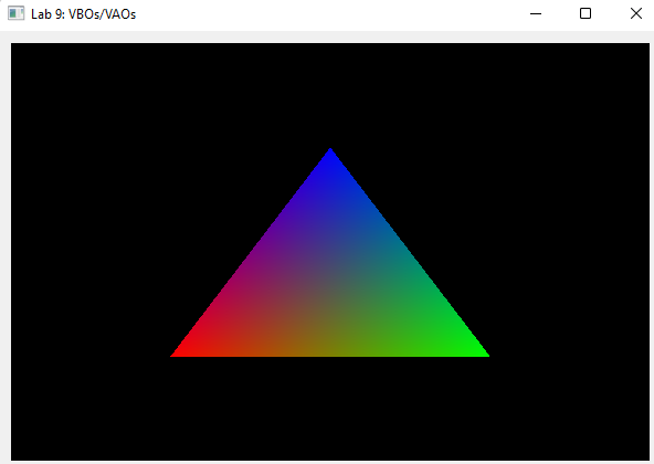
You may wonder how we can pass data from a vertex to a fragment shader, when there are almost always more fragments than vertices.
Each fragment's input value is produced via barycentric interpolation of the output values from the three vertices of the triangle which contain that fragment.
For example, in the figure below (reproduced from Lab 9), the three vertices only have red, green, and blue colors defined on them; these values are interpolated to produce input colors for each fragment.
Uniforms
What if we'd like to provide some data that applies to all vertices/fragments? This is where uniforms come in. Uniforms can be accessed from within shaders using the following declaration:
uniform <data_type> <variable_name>;
Just like how we must declare VAO attributes in the CPU, we must also declare uniforms in the CPU. For this purpose, OpenGL provides a set of functions that start with glUniform.
Depending on the data type, the function signature differs slightly. The generic format of the call is:
// For scalar and vector data:
glUniform_______(GLuint location, <data_to_be_passed>);

// For matrices:
glUniformMatrix_______(GLuint location, <data_to_be_passed>);
Note: the underscores stand in for the size and type of the data (e.g.
glUniform3f()). For a full list of calls for various types, refer to this reference page.
The first argument to this function is the location of the uniform within the OpenGL state machine.
To get this value for a given shader uniform variable, we can use the function glGetUniformLocation.
GLint glGetUniformLocation(GLuint program, const GLchar *name)
program: the unique shader program ID. You got this in task 1, fromShaderLoader.
name: the name of the variable in the shader source code. For example: if you have a uniform calledcolordeclared in the fragment shader, you would use the string"color"for this argument.The returned value is
-1if the specified name cannot be found. Otherwise, we can pass the output GLint directly intoglUniform_as the location parameter.
Important: how to pass matrices as uniforms
This is the function you'll use most often to pass a matrix to the GPU as a uniform variable:
glUniformMatrix4fv(GLint location, GLsizei count, GLboolean transpose, const GLfloat *value)
What does the 4fv suffix mean?
4indicates that the matrix is4x4findicates that the data type isfloatvindicates that the data is a vector (i.e. an array) of matrices. For some reason, there is noglUniformMatrix4ffunction that passes just a single matrix.
This function takes a few more arguments than the glUniform_ functions we've seen so far:
GLsizei count: the number of matrices being passed in. You'll almost always use1here, unless you have reason to pass an array of matrices to your shaders.GLboolean transpose: whether or not to transpose the matrix before passing it in. OpenGL expects the matrix to be in column major order. Luckily,glmalready internally stores its matrices in this format, so when we're passing in aglmmatrix, we can useGL_FALSEhere.const GLfloat *value: a pointer to the first element of the matrix you wish to send. For example: if you have aglm::mat4calledmatrix, you can get this pointer via&matrix[0][0].
Putting this all together: if we wanted to pass in a rotation matrix called rotation:
glUniformMatrix4fv(matrixLocation, 1, GL_FALSE, &rotation[0][0]);
Declare a uniform mat4 variable in the vertex shader to store the model matrix.
Then, in paintGL(), pass in m_model, a member variable storing the model matrix.
Vertex Shaders
As we discussed earlier, a vertex shader is a program that runs on the GPU which operates on each vertex of the VAO that it is processing. In the code you'll be writing for this lab (and later projects), you'll use a vertex shader to apply transformations to vertices.
Transformations In A Vertex Shader
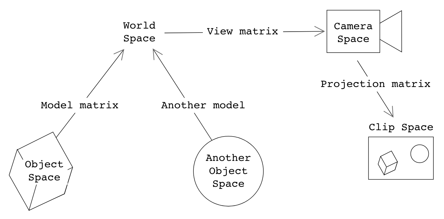
To define the transformations a vertex undergoes from object space to world space, then to camera space, and finally clip space, we use the model , view, and projection matrices.
In previous projects, you only computed model matrices (per-shape) and a view matrix (for the camera)). In OpenGL, however, a third matrix is necessary: we need it to warp our view frustum in camera space into a canonical view volume in clip space.
Naturally, to perform these coordinate transforms, we must pass these matrices into our vertex shader:
As in the previous task, pass m_view and m_proj into the vertex shader as uniforms.
Then, we can apply them to our vertices in the vertex shader:
Compute the world-space position and world-space normal of the vertex, using the model matrix and vertex position you obtained earlier via vertex attributes.
Using these results, set the variables for the world space position and normal you declared earlier using the out keyword.
How do I transform normals, again?
Recall from this lecture that when you transform normals, you have to use the inverse-transpose of the top-left 3x3 portion of the model matrix.
Consider the performance implications of computing this for every single vertex... can you do better in project 5 & 6?
Default Outputs
There is one type of shader output we have not discussed yet: GLSL's "predefined" output variables. These are always implicitly defined by OpenGL. In this case, we only care about gl_Position; you can read about the others here.
gl_Position is a vec4 that represents the vertex's output position in clip space. This is what OpenGL uses to actually place the vertex in the image when rendering. Note that you don't have to declare it yourself, as gl_Position is a built-in OpenGL variable.
Set gl_Position by converting the input object-space position to clip space. Remember to apply the MVP (model, view, projection) transformation's constituent matrices in the correct order!
Wait, aren't we forgetting another step?
You may recall from lecture that, after using the projection matrix, you have to re-homogenize the resulting coordinate to obtain a vertex's proper position in clip space.
Fortunately for us, this is handled by OpenGL!
Fragment Shaders
As mentioned before, the fragment shader runs after the rasterization step of the pipeline, where each triangle has been converted into a set of fragments for each pixel that the triangle covers. The fragment shader then computes the color of each fragment, given some interpolated inputs passed from the vertex shader.
"Default" Outputs
You might expect that just like vertex shaders have a default output called gl_Position, fragment shaders would have a similar default output. They used to, but this has been deprecated; now, all fragment shader outputs are specified explicitly with out variable declarations.
For the purposes of this lab (and most of the code you'll write in this course), this means you need to declare an out vec4 variable and assign to it in the fragment shader's main() function. This output is then detected by OpenGL and is assumed to be the final output pixel color. This variable name does have the restriction of not being allowed to begin with gl_ however, so be careful!
Extra: more on fragment shader outputs
When we said "this output is then detected by OpenGL and is assumed to be the final output pixel color," we swept quite a bit under the rug. OpenGL can actually be configured to render images with many different output channels, each of which might be associated with a different fragment shader output. You can read more about the details behind fragment shader outputs here: https://www.khronos.org/opengl/wiki/Fragment_Shader#Outputs
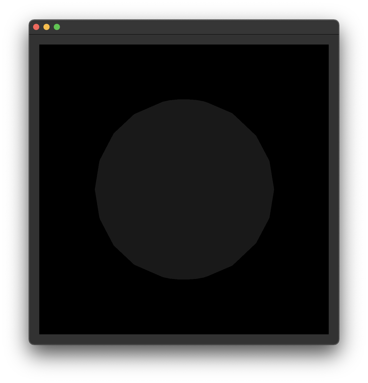
Manually add a vec4 named fragColor as an output to your fragment shader. For now, set it to vec4(1.0) in the fragment shader's main() function.
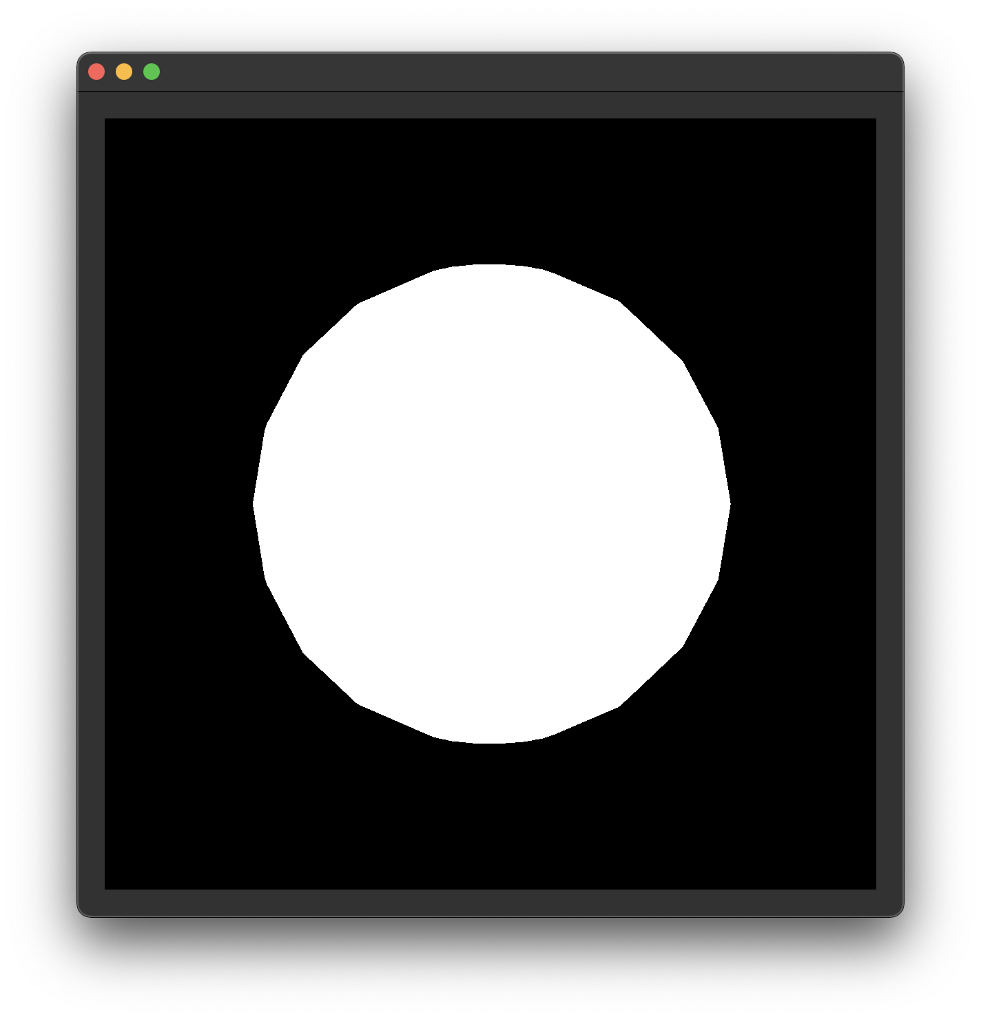
You should now see a white circle like the one above when you run your code (if you don't, it's time to debug... 😔).
Next, to verify your normals are correct, use the absolute value of your normal input variable's x, y and z components as the r, g, and b components of your fragment shader output.
As a hint, the following pattern is allowed in GLSL: someVec4 = vec4(abs(someVec3), 1.0).
After you're done, set the output color to black (i.e. vec4(0.0)) to get ready for the next part of the lab. This is optional—you won't need this if you just overwrite your output color later.

Phong Illumination
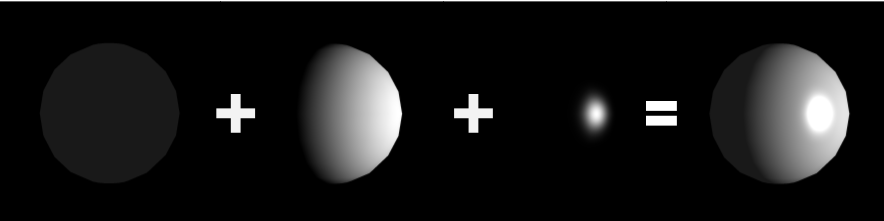
Now that we've gone over the basics of vertex and fragment shaders, we're going to implement a basic version of the Phong illumination model.
You can think of the lab up to now as a "tutorial"—but, from here on out, you'll be tasked with applying what you learned in a less guided environment. Make sure to reference earlier parts of the lab if you get stuck!
Here's the lighting equation you'll be using:
Note that this is a simplified model compared to the one you implemented in the Ray projects: it doesn't deal with color or attenuation, and it assumes only one point light source.
Ambient Lighting
To add the ambient component of our illumination model, we can use
You are given m_ka, a member variable in the GLRenderer class. Add this float value to your fragment shader's output color.
Hint: Step-by-step process
Please try these tasks on your own first, and only look at the hints if you get stuck!
You will have to perfectly understand this process by the time you work on project 5.
- Declare a uniform float
k_ain the fragment shader, to hold the ambient coefficient. - Pass
m_kainto the shader from the CPU as a uniform. - Finally, set your output color to a
vec3with components equal tok_a.
Diffuse Lighting
Next, let's add the diffuse component of the illumination model to our shader.
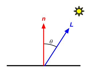
Recall that the diffuse component in our simplified Phong model is
is the diffuse coefficient, is the surface normal, and is the surface-to-light direction
In our fragment shader, besides
We'll also need our surface position and normal. Good thing we passed these from our vertex shader to our fragment shader! But, we have to be careful:
When passing a vector from the vertex shader to the fragment shader, the process of rasterization and interpolation can change the length of the vector.
It is therefore necessary to renormalize vectors in the fragment shader if you expect them to be normalized!
You are given m_kd and m_lightPos as member variables in the GLRenderer class.
Use this information to add the diffuse component of the Phong lighting equation to your fragment shader's output color.
- You might find the dot and normalize functions useful. These are built into GLSL.
- Remember to clamp your dot product result to
[0, 1].
Hint: Step-by-step process
Please try these tasks on your own first, and only look at the hints if you get stuck!
You will have to perfectly understand this process by the time you work on project 5.
- In your fragment shader, declare the following uniforms:
- A
uniform floatto hold the diffuse coefficient, and - A
uniform vec4to hold the world-space light position.
- A
- In
paintGL(), pass the following into your shader:m_kd, andm_lightPos.
- Back in your fragment shader, calculate the surface-to-light direction vector
. - Then, calculate the diffuse intensity using
dot()and theand the surface normal. Remember to normalize()those vectors beforehand! - Finally, add the diffuse intensity to the output color.
Specular Component
Finally, let's add the specular component of the illumination model to our fragment shader.
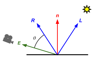
Recall that the specular component in our simplified Phong model is
is the specular coefficient, is the reflected light vector, is the surface-to-camera direction, and is the specular exponent (aka shininess).
This is just more of the same from the previous task. You can surely figure it out!
You are given m_ks and m_shininess as member variables in the GLRenderer class.
You are not given the camera position, but you do already have a m_view... How can you get the camera's position? Should you compute it in the CPU, or in your shader?
Use this information to add the specular component of the Phong lighting equation to your fragment shader's output color.
- You might find the pow and reflect functions useful. These are built into GLSL.
- Remember to clamp your dot product result to
[0, 1].
Hint: Step-by-step process
Please try these tasks on your own first, and only look at the hints if you get stuck!
You will have to perfectly understand this process by the time you work on project 5.
- In your fragment shader, declare the following uniforms:
- A
uniform floatto hold the specular coefficient, - A
uniform floatto hold the shininess, and - A
uniform vec4to hold the world-space camera position.
- A
- In
paintGL(), pass the following into your shader:m_ks,m_shininess, and- The world-space camera position, obtained using by applying
inverse(m_view)on the origin.
- Back in your fragment shader, calculate the reflected light vector
in the fragment shader using the reflect()function. - Next, calculate the surface-to-camera direction vector
. - Then, calculate the specular intensity using
dot()and the two vectors above, as well as the exponential functionpow(). - Finally, add the specular intensity to the output color.
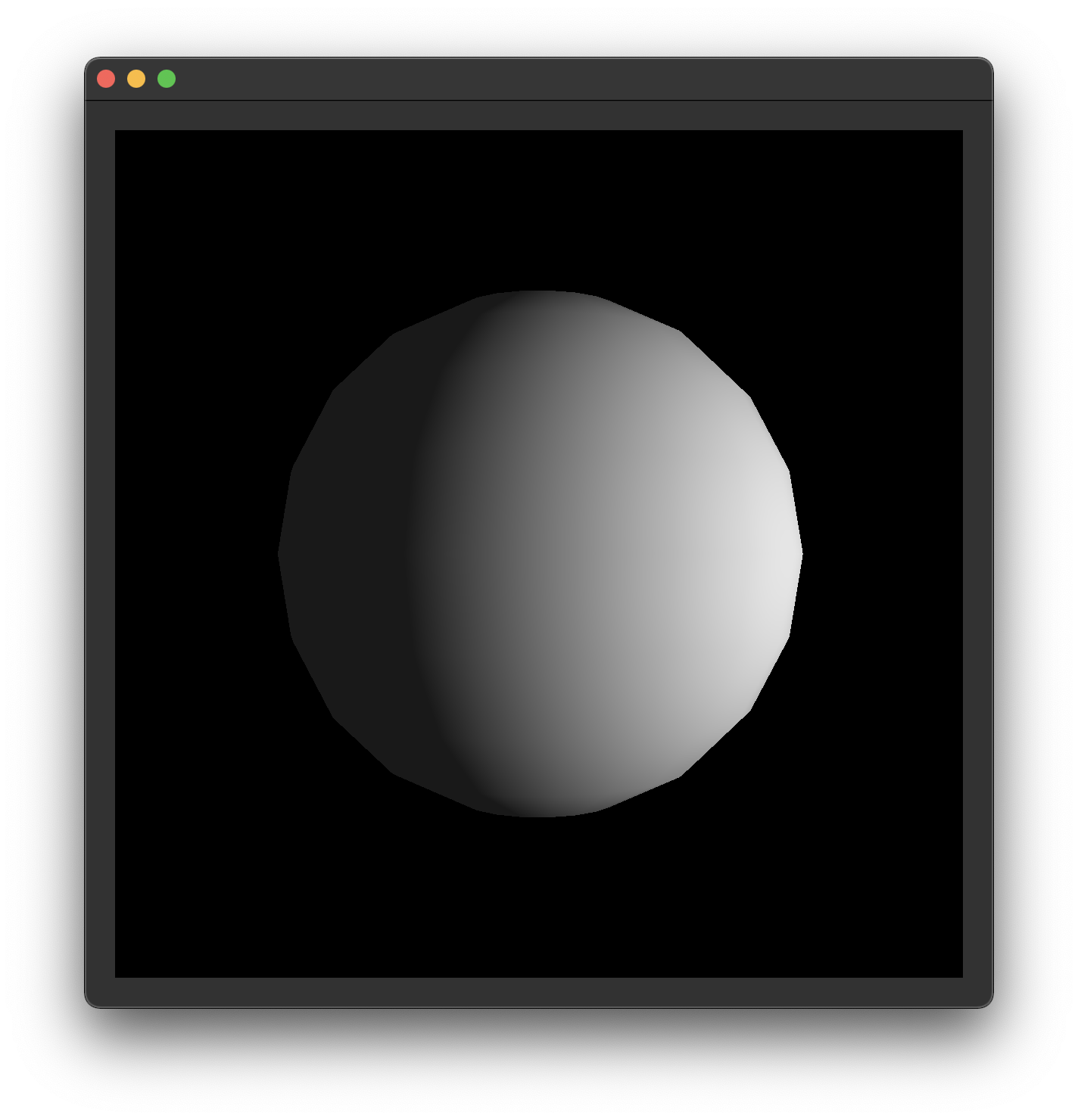
End
Congrats on finishing the Shaders lab!

Once your output looks like this, it's time to submit your code and get checked off by a TA.
Submission
Submit your GitHub link and commit ID to the "Lab 10: Shaders" assignment on Gradescope, then get checked off by a TA at hours.
Reference the GitHub + Gradescope Guide here.