Project 4: Illuminate
Github Classroom assignment (same assignment as before)
You can find the section handout for this project here.
Please read this project handout before going to algo section!
Introduction
In Intersect, you saw a glimpse of what the raytracing algorithm can do. However, our rendered images are still rather plain. So, in Illuminate, you will build upon your previous code by implementing more complex lighting effects, shinier surfaces, shadows, and texture mapping. You're well on your way to having a fully-fledged raytracer!
Requirements
For this project you will need to extend your raytracer with the following features:
Light Sources
Previously, you implemented the Phong illumination model with directional lights. In this project, you are required to implement the interaction between objects and two new types of light sources: point lights and spot lights. All light sources are parsed from the scenefiles that we provide. Each light source has light intensity values and its own specific parameters.
Point lights and spot lights also have attenuation coefficients, so you will need to account for attenuation in your Phong illumination calculations.
Point Lights
A point light is an infinitesimal point in space that emits light equally in all directions. You can understand its characteristics by imagining a light bulb whose volume is condensed to a single point. This light source's specific parameter is its position in space.
Spot Lights
A spot light is a point in space that emits light in a finite cone of directions. A good example of spot light in real life is a flashlight.
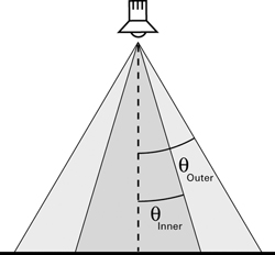
In this project, you are required to implement spot lights with angular falloff: the effect of light intensity becomes weaker as the direction to the point being illuminated diverges from the direction in which the spot light faces. The figure below illustrates the effect. The boundary of the whole region illuminated by the spotlight is called the outer cone. Within the outer cone, there is a smaller region where light intensity is full; the boundary of this region is called the inner cone. In the region between inner and outer cone, the light intensity gradually decreases as light direction approaches the edge of the outer cone.
There are many different falloff functions with different effects. For this project, we suggest you use the following function because of its smooth transitions at the boundaries:
The symbols used in this equation are explained in the table below.
| Symbol | What It Represents |
|---|---|
| the full light intensity of the spotlight | |
| the light intensity at a given direction | |
| the falloff function | |
| the angle between inner cone boundary and spotlight direction | |
| the angle between outer cone boundary and spotlight direction | |
| the angle between current direction and spotlight direction |
This light source's specific parameters include its position, direction, angle (angular size of outer cone, in radians) and penumbra (angular size of of the region between the inner and outer cone, in radians).
Adding Attenuation To Phong Lighting
Attenuation is the reduction in the intensity of light as it propagates further from a light source. You are required to add this effect to the Phong illumination model that you have previously implemented. Here is the extended Phong illumination model equation with attenuation. Notice that the attenuation factor works on both diffuse and specular components.
Click here for a full breakdown of the equation's terms.
| Subscript | What It Represents |
|---|---|
| A given wavelength (either red, green, or blue). | |
| A given component of the Phong illumination model (either ambient, diffuse, or specular). | |
| A given light source, one of |
| Symbol | What It Represents |
|---|---|
| The intensity of light. E.g. | |
| A model parameter used to tweak the relative weights of the Phong lighting model's three terms. E.g. | |
| A material property, which you can think of as the material's "amount of color" for a given illumination component. E.g. | |
| The total number of light sources in the scene. | |
| The surface normal at the point of intersection. | |
| The normalized direction from the intersection point to light | |
| The reflected light of | |
| The normalized direction from the intersection point to the camera. | |
| A different material property. This one's called the specular exponent or shininess, and a surface with a higher shininess value will have a narrower specular highlight, i.e. a light reflected on its surface will appear more focused. | |
| The attenuation factor. |
The attenuation factor should be calculated according to the equation below. function field of SceneLightData.
Shadows
Shadows occur when part of a surface is blocked from the light source by other objects. In this project, you are required to take shadows into account when implementing lighting.
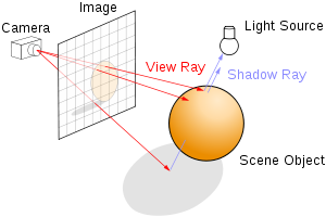
The key to adding shadows is to judge whether a light source is visible from an intersection point for which you are computing lighting. For this assignment, you are only required to implement "hard shadows," where a surface point completely ignores any contribution from a light source which it cannot see. But be careful to take the characteristics of different types of light sources into account. You may discover more interesting ways to add shadows in the Extra Credit section.
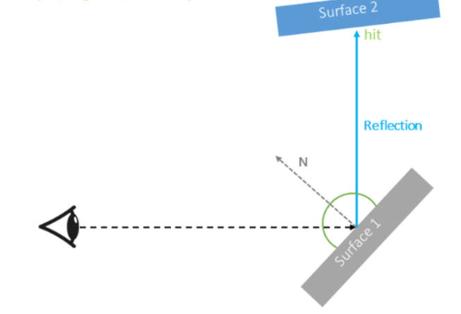
Reflection
Smooth, polished surfaces in the real world often exhibit mirror-like reflections. In this project, you are required to implement this effect via recursive raytracing (i.e. tracing a ray in the mirror reflection direction about a surface normal). As such reflections only occur on shiny surfaces, you should only enable reflections for objects which have a nonzero reflective material component (reflections are a recursive process, so we want to prevent unnecessary calculations).
In scenes with multiple specular surfaces, it is possible for reflection rays to bounce recursively many (potentially infinitely many) times.
To avoid infinite loop / recursion, you probably want to have a maximum depth. For reference, the TA demo uses maximum-recursive-depth.
Texture Mapping
With texture mapping, you can vary the material properties of an object across its surface. This allows us to simulate objects that have a more complicated appearance than just a solid color.
UV Coordinates
To put a texture onto a surface, each point on the surface must map to a corresponding point in the texture image. These per-point image coordinates are called UV coordinates. For example, on each face of a cube, the UV coordinate system may originate from the left bottom corner and use the left and bottom edges of the face as its axes. You should think about how that applies to other shapes (e.g. cylinders, spheres, cones) on your own. Refer to the surface parameterization section of the texture mapping lecture slides for further guidance.
Blending
Another aspect of texture mapping is how the texture image interacts with the material properties for the surface specified in the scene file.
A blend value is supplied as a material property for objects that are texture mapped.
- If the blend value is 1, then the texture entirely replaces the diffuse color of the object.
- If the blend value is 0, then the texture will be invisible.
- If the blend value is between 0 and 1, then you should perform linear interpolation between the diffuse color and the texture. Note: the diffuse color you are blending with should have already been multiplied by global diffuse coefficient.
All of our scenefiles and textures are in the scenefiles folder. Texture images in the scenefiles are specified by their relative paths, so please don't move any files around within the folder. To help you with this, we have provided an interface for you
to load image data from a given path in utils/imagereader.h.
Texture Filtering
For this assignment, you only need to use nearest-neighbor for texture filtering to retrieve the color from a texture image at a given UV coordinate. More sophisticated texture filtering approaches can be implemented for extra credit.
Codebase & Design
Your work on this project will extend your code from the Intersect project; there is no additional stencil code.
We have provided the data structures for object material and light sources in SceneData.h, which you may already have noticed.
As before, the structure of this project is entirely up to you: you can add new classes, files, etc. However, you should not alter any command line interfaces we have implemented in the code base.
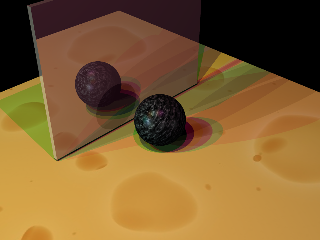
We provide all the rendered results of the scenes we have in the scenefiles folder under illuminate/required_outputs, illuminate/optional_outputs, and illuminate/extra_credit_outputs.
They serve as references for you to check the correctness of your implementation.
You may notice that features like shadows, reflection and many other extra credit features are part of the config that is specified in the QSettings file,
which indicates that they should be able to be toggled on / off based on the input configuration. We expect your implementation to respect this behavior.
If you implement any additional extra credit feature that is not covered by the template config , make sure to rememeber adding the additional flag to
your RayTracer::Config and document it properly in your README
We also provide an automated script, run-illuminate.sh, included in the stencil, to run your ray tracer on all required scenes for submission. This script is compatible with macOS, Linux, and Git Bash on Windows. To run it, make sure
you have built a Release version of your project in Qt, and then simply run:
sh run-illuminate.sh
Scenes Viewer
To assist with creating and modifying scene files, we have made a web viewer called Scenes. From this site, you are able to upload scenefiles or start from a template, modify properties, then download the scene JSON to render with your raytracer.
We hope that this is a fun and helpful tool as you implement the rest of the projects in the course which all use this scenefile format!
For more information, here is our published documentation for the JSON scenefile format and a tutorial for using Scenes.
TA Demos
Demos of the TA solution are available in this Google Drive folder. projects_illuminate_min is the "minimum" solution with the baseline requirements complete. projects_illuminate_max is the "maximum" solution with all of the extra credit features implemented.
macOS Warning: "____ cannot be opened because the developer cannot be verified."
If you see this warning, don't eject the disk image. You can allow the application to be opened from your system settings:
Settings > Privacy & Security > Security > "____ was blocked from use because it is not from an identified developer." > Click "Allow Anyway"
Instructions for Running
You can run the app from the command line with the same .ini filepath argument that you would use in QtCreator. You must put the executable inside of your build folder for this project in order to load the scenefiles correctly.
On Mac:
open projects_illuminate_<min/max>.app --args </absolute/filepath.ini>
On Windows and Linux:
./projects_illuminate_<min/max> </absolute/filepath.ini>
Grading
For points deducted regarding software engineering/efficiency in your implementation of Project 3: Intersect, you will have the same points deducted again for this part of the project if these are not corrected.
This assignment is out of 100 points.
- Point Lights (5 points)
- Spot Lights (10 points)
- Attenuation (5 points)
- Reflection (15 points)
- Shadows (20 points)
- Texture Mapping (25 points)
- Software engineering, efficiency, & stability (20 points)
Remember that filling out the submission-illuminate.md template is critical for grading. You will be penalized if you do not fill it out.
Extra Credit
All of the extra credit options from Intersect are also valid options here (provided you haven't already done them for Intersect). In addition, you can consider the following options (or come up with your own ideas):
- Texture filtering: nearest-neighbor filtering when retrieving texture values generates unsatisfying results when texture image resolution and surface size are very different in scales. You can use more advanced filtering methods to improve the results. For example:
- Bilinear filtering (up to 2 points)
- Bicubic filtering (up to 4 points)
- Refraction (up to 10 points): Simulate the effect of light transmitting through a semi-transparent objects. To receive credit for this feature, you must take Snell's law into effect and bend the refracted light rays according to the object's index of refraction (you may want to add an index of refraction material parameter to each object).
- Depth of field (up to 10 points): Rather than use a pinhole camera (i.e. a camera represented by an infinitesimal point in space), implement a camera with a finite-area lens. By sampling different origin locations for rays on this lens, you can create depth-of-field defocus blur in your scene. Keep in mind that with this method, the image plane (i.e. where rays cross through pixels) defines the plane at which the scene is in focus, so you may want to play with pushing this plane farther into your scene than you previously considered.
- Soft shadows (up to 10 points): Implement a new type of light source with a finite area (this could be as simple as a rectangle sitting somewhere in your scene). Then, when you need to shoot shadow rays toward this light source, sample a random location on the light source for the shadow ray to be traced toward. By sampling different locations on the light source, you can create soft shadows in your scene.
CS 1234/2230 students must attempt at least 10 points of extra credit.
FAQ & Hints
The colors in my rendered images look different from the reference images.
The color from lighting is affected by many factors: surface normals, object materials, light sources, global coefficients, etc. You can try to validate the correctness of most factors by setting breakpoints and checking intermediate variables. You can validate them with manually calculated values in the simplest scenes.
Debugging can be hard. Be patient and creative!
My images have many black dots.
This may be due to shadow rays intersecting their starting surface. Check if your code correctly prevents such erroneous self-intersections.
My ray tracer runs very slowly :(
We've provided some hints on how to address such issues in the Intersect handout.
Milestones
Although how you approach the steps of the project is entirely up to you, we have provided a rough milestone of steps to help you code incrementally. Since this is a just an outline, please double check the submission requirements to ensure you have completed all necessary functionalities.
Week 1:
- Implement point and spot light
- Consider how the addition of position in these lights affects implementation
- Incorporate the attenuation factor for these lights
- Implement shadows
- Double check edge cases (consider distance relationships between the intersection points and lights)
Week 2:
- Implement reflections and incorporate into the lighting calculations
- Consider how you can refactor your code to reuse ray casting logic and support recursion
- Implement texture mapping
- Calculate the uv coordinates for each shape
- Blend the texture with the diffuse color of the shape
Submission
Submit your GitHub repo and commit ID for this project to the "Project 4: Illuminate (Code)" assignment on Gradescope.
Your repo should include a submission template file in Markdown format with the filename submission-illuminate.md. We provide the exact scenefiles
you should use to generate the outputs. You should also list some basic information about your design choices, the names of students you collaborated with, any
known bugs, and the extra credit you've implemented.
For extra credit, please describe what you've done and point out the related part of your code. If you implement any extra features that requires you to add a parameter for QSettings.ini and RayTracer::Config, please also document it accordingly so that the TAs won't miss anything when grading your assignment.