Project 5: Realtime
When cloning the stencil code for this assignment, be sure to clone submodules. You can do this by running
git clone --recurse-submodules <repo-url>
Or, if you have already cloned the repo, you can run
git submodule update --init --recursive
You can find the section handout for this project here.
Please read this project handout before going to algo section!
Introduction
In the Ray assignments, you implemented a ray tracer that projects a 3-dimensional scene on a 2-dimensional plane. Ray tracing, as you probably have experienced, can be very slow.
In this assignment, you will design a real-time scene viewer using components from previous labs including Parsing, Transformations, Trimeshes, VAOs, and Shaders.
Requirements
Parsing the scene
Similarly to Ray, you will use the same scene parser from Lab 4: Parsing to read in scenefiles. You are expected to call your scene parser to get your metadata and set up the scene as you see fit when new scenes are loaded in. Note that you will no longer be using .ini files and will rather just use .json files directly!
Refer to section 3.1 for more information on how to work with the parser and deal with scene changes in the codebase.
Shape tessellation
In Lab 8: Trimeshes, you should have implemented tessellation for three shapes: cube, cone and sphere. In this project, you are expected to also include tessellation for cylinder. The descriptions of these shapes remain the same as in Project 2: Intersect:
- Cube: A unit cube (i.e. sides of length 1) centered at the origin.
- Sphere: A sphere centered at the origin with radius 0.5.
- Cone: A cone centered at the origin with height 1 whose bottom cap has radius 0.5.
- Cylinder: A cylinder centered at the origin with height 1 whose top and bottom caps have radius 0.5.

The tessellation parameters should control the vertical and radial tessellations just as they do for the sphere. As a reminder, parameter 1 controls tessellation along the latitude direction while parameter 2 controls tessellation along the longitude direction.
We recommend working on these shapes in your lab 8 stencil prior to porting them into Project 5: Realtime.
This will allow you to use the visualizer to debug position and normals.
While the specifics of your tessellation code are up to you, you are expected to design your program in an extensible, object-oriented way. This means minimal code duplication and no 400 line branch structures (such as if... else... statements). You will lose points if you do not follow these guidelines.
Your shapes should never disappear when the tessellation parameters are too low! Be sure to set minimum tessellation parameters appropriate to each shape accordingly.
Camera
Your camera for the raytracer only needed to produce a view matrix. For Project 5: Realtime, you must produce both view and projection matrices given the scene file's camera parameters. The projection matrix is needed to convert from camera space to clip space for OpenGL to render the scene correctly.
To implement your projection matrix, you may not use glm::perspective.
Keep in mind you are able to edit the near & far plane distances in real-time. These are seen in the parameters: settings.nearPlane and settings.farPlane. Be sure to update your camera accordingly when these parameters change!
Data Handling
Welcome to the meat and potatoes of this project!
You will use everything you have learned from lecture and labs to use the OpenGL pipeline to manipulate and keep track of scene data. You will take your parsed scene metadata and use it to construct all necessary VAO/VBO objects. Then you will use these in the main render loop of paintGL to finally render the scene, while integrating materials, global data, and light data as uniforms.
As far as the design goes, some questions you might want to ask are:
- How will I represent my shape data in OpenGL?
- What do my VAOs and VBOs need to be able to do/How can I generalize what I did in lab 9?
- How will I use my parsed RenderData to draw my scene in
paintGL? - How many VBO/VAOs will I need in each scene? Is it dependent on the scene?
- Please do not include more VBOs and VAOs than necessary! For example, two separate VBOs should not store the same data. Points will be deducted for excess memory usage.
In general, filling
realtime.cppwith all of yourgl_____calls is likely bad code design and will make debugging MUCH MORE DIFFICULT!
Shaders
For this project, your shader program should have the following features:
- Support for...
- Direction Lights
- Point Lights w/ Attenuation
- Spot Lights w/ Attenuation & Penumbra
- Ambient, diffuse, and specular intensity computation
- Final color computation integrating both object and light color
- Support for up to 8 simultaneous lights. (See subsection below)
Of course, your shaders must also perform all the necessary coordinate space conversions (think MVP matrices) as well as the illumination model computation. Think about how all of your scene data will integrate with your shaders! Which parts can you do in the Fragment shader, which parts can you do in the Vertex shader?
As such, it is important to have completed Lab 10: Shaders before attempting this part of the project.
Point Lights: Similar to Ray, these lights are defined by their position and follow a standard quadratic attenuation fall off given by
where function.
Spot Lights: Using the same mathematics as in the Ray projects, these lights follow not only the standard distance falloff, but an additional angular falloff defined by angle and falloff in the stencil light object.
Arrays and Structs in GLSL
In Lab 10: Shaders, you learned about various uniforms to use CPU data in a shader. When dealing with multiple identical objects, the common approach is to immediately think about arrays. In GLSL, an array of vec3s looks like this:
uniform vec3 myVectors[8];
Notice how this array is of fixed size 8, specified explicitly in code. This is because GLSL does not support dynamically sized arrays! And it's also why we require you to support an explit number of lights.
You can access element i in this array as follows:
vec3 myithElement = myVectors[i];
The next question you may have is how to actually pass data into a uniform array. For example, to fill in the (x, y, z), you would write the following:
GLint loc = glGetUniformLocation(shaderHandle, "myVectors[" + std::to_string(j) + "]");
glUniform3f(loc, x, y, z);
If you wish to get fancy, you can try using structs as well. They have to be first defined in the shader then declared as a uniform in the following manner:
struct AwesomeStruct
{
  int favoriteNumber;
  vec3 favoriteColor;
};

uniform AwesomeStruct myStruct;
Accessing the member favoriteColor from the uniform is done as such:
vec3 coolestColor = myStruct.favoriteColor;
To set the color data to a vector (r, g, b), you would write the following:
GLint loc = glGetUniformLocation(shaderHandle, "myStruct.favoriteColor");
glUniform3f(loc, r, g, b);
If you wish to read more about uniform in GLSL, check out this link!
Special tip about GLSL
In GLSL, pow(x, y) is undefined for shininess = 0! Check the official document to learn more.
Camera Movement
For translational movement, your input and output will be required to match the following:
- W: Translates the camera in the direction of the look vector
- S: Translates the camera in the opposite direction of the look vector
- A: Translates the camera in the left direction, perpendicular to the look and up vectors
- D: Translates the camera in the right direction, also perpendicular to the look and up vectors. This movement should be opposite to that of pressing A
- Space: Translates the camera along the world space vector
- Ctrl: Translates the camera along the world space vector
We would like you to move at a speed of 5 world-space units per second. Use the deltaTime parameter in the timerEvent function to help achieve this.
For rotational movement, your input and output will be required to match the following:
- Mouse X Distance Traveled: Rotates the camera about the axis defined by the world space vector
- Mouse Y Distance Traveled: Rotates the camera about the axis defined by a vector perpendicular to the look and up vectors of the camera.
- Mouse Left Click: ONLY apply camera rotations if the left mouse button is currently held. This is similar behavior to the brush project so feel free to look back at your old code for inspiration.
Hint: A perpendicular vector to two other vectors can be calculated by taking a cross product!
While we don't force a specific speed for rotation due to wide variance in mice sensitivity, your rotation must be dependent on the distance the mouse has traveled which is given as deltaX and deltaY within mouseMoveEvent.
You may notice there are a few things left up to your discretion. Whether you rotate CW or CCW on mouse movement as well as sensitivity is up to you, as long your implementation follows the general guidelines above.
In particular, we have provided for you 6 different event functions you may find useful for this task:
mousePressEvent, mouseReleaseEvent, mouseMoveEvent, keyPressEvent, keyRepeatEvent, keyReleaseEvent.
Important: You may NOT use the following GLM functions--we expect you to have a good enough understanding of transform matrices to construct helper functions for each of these if necessary:
glm::scale()glm::rotate()glm::translate()
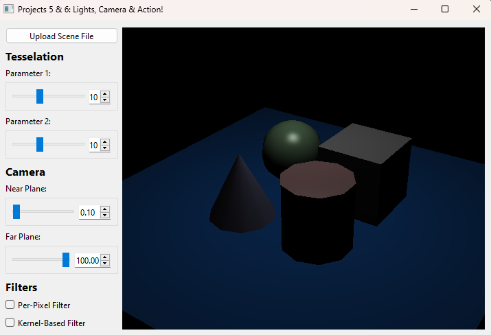
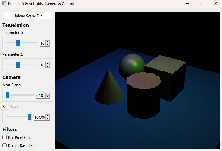
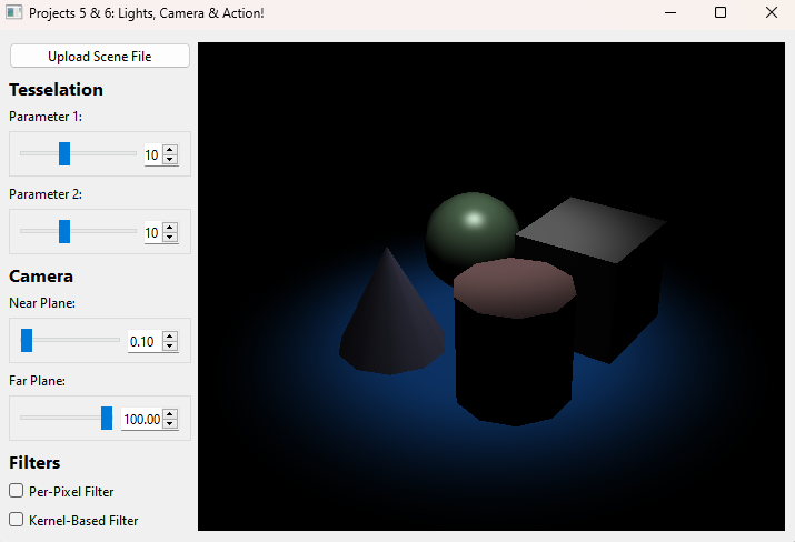
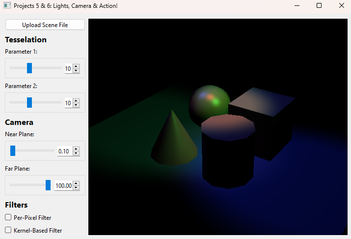
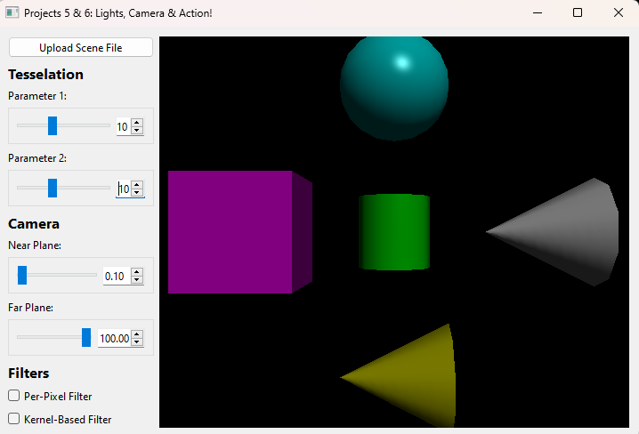
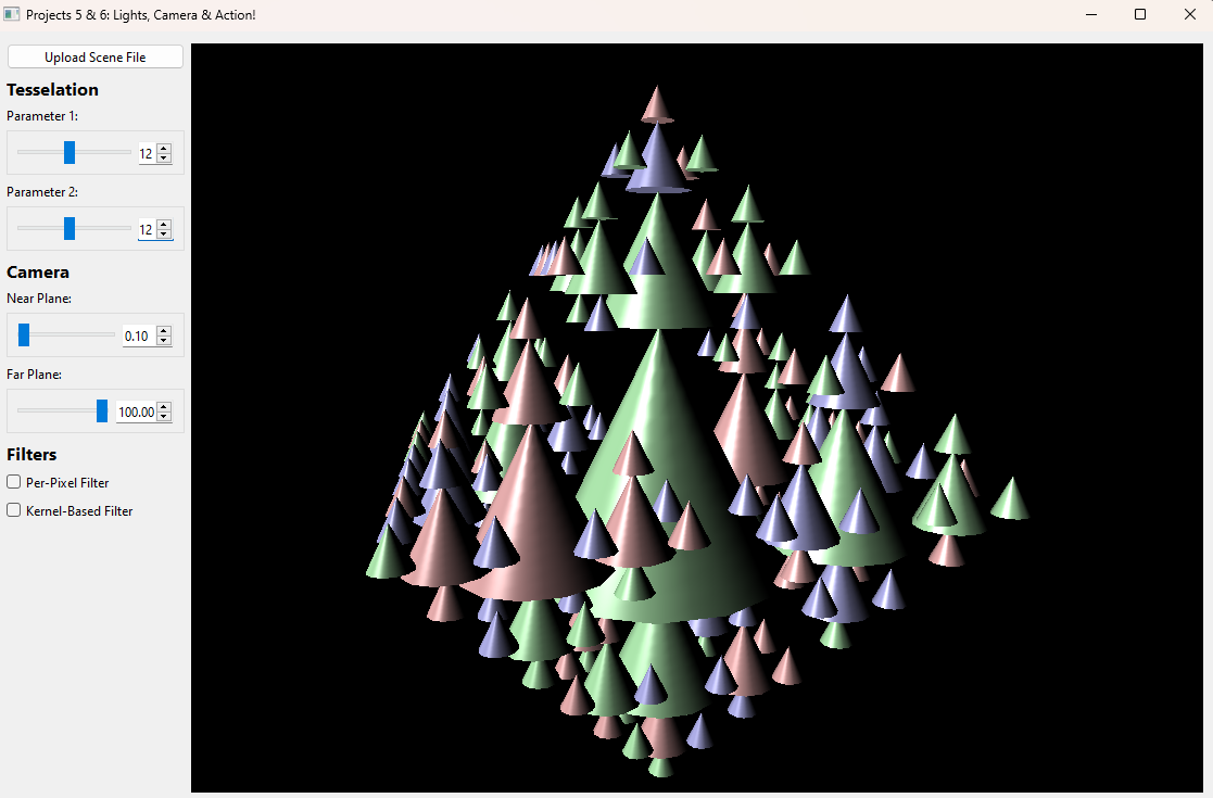
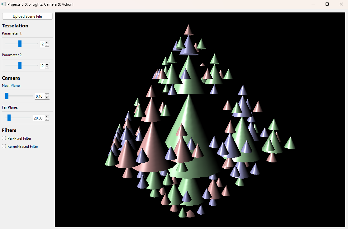
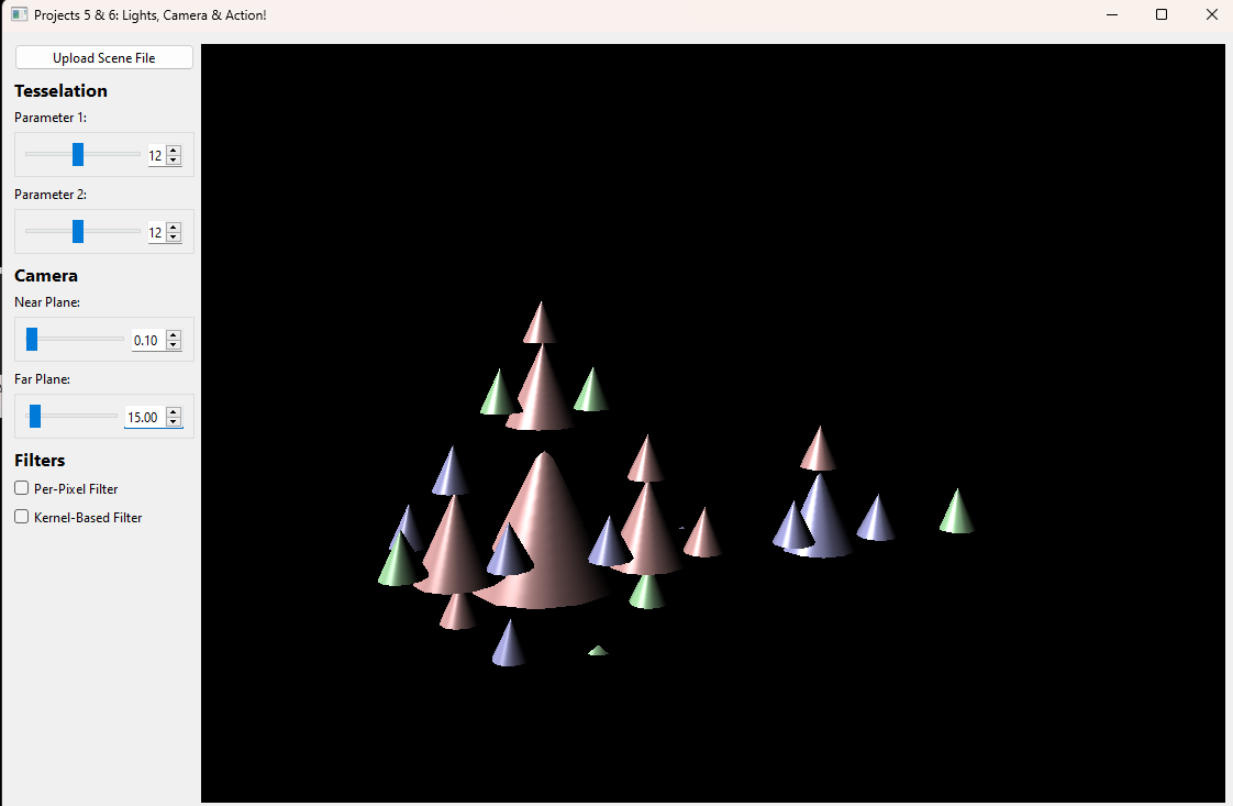
Results
Here are some sample images of what your realtime renderer should be capable of by the end of this assignment.

GLM Library Functions
Please avoid using the following GLM functions, since we cover how to implement them in class. Some of these have already been mentioned in the handout, so pay special attention to those!
-
glm::lookAt(eye, center, up) -
glm::reflect(I, N) -
glm::perspective(fovy, aspect, near, far) -
glm::mix(x, y, a) -
glm::distance(p1, p2) -
glm::scale(mat, vec) -
glm::rotate(mat, angle, axis) -
glm::translate(mat, vec)
If you used scale(), rotate(), or translate() in Lab 4: Parsing, you may continue to do so. The restriction here only applies to new code you write for this project!
Stencil Code
You may notice the stencil code provided is minimal--that is by design. To complete this assignment, you will need to have a good understanding of the OpenGL pipeline.
We have provided for you the following files which you will interact with:
Realtime: A file containing the initialization of an OpenGL context as well as functions that are automatically called on certain events. These include:initializeGL,paintGL, andresizeGL.Settings: initialized from an.xmlfile along with any gui sliders/checkboxes which are updated in realtime.
And you have already written the following:
Working with GLEW and OpenGL in Qt:
If you are working in a file and need to use OpenGL functions, make sure to use #include <GL/glew.h>!
Also, Qt creator gives you access to the OpenGL context when calls stem from any of: Realtime::initializeGL(), Realtime::paintGL(),
and Realtime::resizeGL(). If you wish to make OpenGL calls stemming from outside these functions (for example Realtime::sceneChanged()),
you must call makeCurrent() first.
Loading Scenes
As stated before, you will need to handle the loading of scenes using your scene parser from lab 4.
We have provided for you a helper function in realtime.cpp for you to use for this purpose titled sceneChanged().
This function will be called whenever the "Upload Scene File" button is pressed and a .json file is selected.
To get access to the current scenefile, you can use the settings object's sceneFilePath parameter.
Important: We will not be working with .ini files in this project! Given the real-time nature of this
project, settings and parameters will be controlled by interactive UI buttons and sliders instead.
Realtime::initializeGL(), Realtime::paintGL(), & Realtime::resizeGL()
These functions are the "core" of a rendering system. They are overriden from the parent QOpenGLWidget class if you are interested.
-
intializeGL()is called once near the start of the program after the constructor ofRealtimehas been called. It also is called before the first calls topaintGL()orresizeGL(). However, you cannot use any draw calls in this function. Rather, use it to initialize any OpenGL related information you may need, after the GLEW initialization calls as commented. Note that you cannot use any OpenGL-related functions in the constructor of this class as they are only available once GLEW has been initialized. -
paintGL()is called whenever the OpenGL context changes, i.e. when you make some state-altering OpenGL call. -
resizeGL()is called whenever the window is resized. You will need to use the inputwidthandheightto correctly update your camera.
Realtime::finish()
In OpenGL, we often use calls of the form glGen______. Just as with using the keyword new, we must delete this generated memory as well.
This function, finish(), will be called just before the program exits so be sure to use it to your advantage to avoid memory leaks!
Realtime::settingsChanged()
In general, this function will be called any time a parameter of the settings is changed (via interacting with the left GUI bar) other
than settings.sceneFilePath.
For this project, the settings you will have to worry about are:
settings.nearPlane: Should control your camera's near clipping plane.settings.farPlane: Should control your camera's far clipping plane.settings.shapeParameter1: Should control the tessellation parameter 1 as described in section 2.2 above.settings.shapeParameter2: Should control the tessellation parameter 2 as described in section 2.2 above.
Realtime::____event() Functions
For these functions, there are really only 2 you should need to use for this project: mouseMoveEvent and timerEvent.
timerEvent is called on a loop which is attempting to run 60 times per second. However because loops can never be perfect, we have calculated for you the time between loops labeled in a variable deltaTime which you can use for translational movement.
mouseMoveEvent is called whenever the mouse moves. We have calculated in this function for you deltaX and deltaY which tell you how far the mouse has moved. In addition, we have also applied a variable m_mouseDown which lets you know if the left mouse button is currently clicked.
m_keyMap
A new member variable that will be useful to you is labeled m_keyMap. This is an std::unordered_map containing Qt::Keys as the key and a boolean representing whether or not the key is currently pressed down at any given time. One example of how to use this member variable is:
m_keyMap[Qt::Key_W]: Returns whether or not the "W" key is pressed down
m_keyMap comes equipped to handle the keys: Qt::Key_W, Qt::Key_A, Qt::Key_S, Qt::Key_D, Qt::Key_Space, and Qt::Key_Control.
Scenes Viewer
To assist with creating and modifying scene files, we have made a web viewer called Scenes. From this site, you are able to upload scenefiles or start from a template, modify properties, then download the scene JSON to render with your raytracer.
We hope that this is a fun and helpful tool as you implement the rest of the projects in the course which all use this scenefile format!
For more information, here is our published documentation for the JSON scenefile format and a tutorial for using Scenes.
TA Demos
Demos of the TA solution are available in this Google Drive folder.
macOS Warning: "____ cannot be opened because the developer cannot be verified."
If you see this warning, don't eject the disk image. You can allow the application to be opened from your system settings:
Settings > Privacy & Security > Security > "____ was blocked from use because it is not from an identified developer." > Click "Allow Anyway"
Grading
This project is out of 100 points:
- Camera data (10 points)
- View matrix (2 points)
- Projection matrix (8 points)
- Camera Movement (10 points)
- Translation on Key Press (5 points)
- Rotation on Mouse Movement (5 points)
- Cylinder shape implementation (10 points)
- Shaders (40 points)
- Phong illumination (20 points)
- Point Lights w/ Attenuation (5 points)
- Spot Lights w/ Penumbra (10 points)
- Support for multiple lights (5 points)
- Tessellation (responds to changes in parameters) (10 points)
- Software engineering, efficiency, & stability (20 points)
Remember that filling out the submission-realtime.md template is critical for grading. You will be penalized if you do not fill it out.
Extra Credit
To earn credit for extra features, you must design test cases that demonstrate that they work. These test cases should be sufficient; for example:
- If you implement a feature that has some parameter, you should have multiple test cases for different values of the parameter.
- If you implement a feature that has some edge cases, you should have test cases that demonstrate that the edge cases work.
- If your feature is stochastic/ has non-deterministic behavior, you should show examples of different random outputs.
- If your feature is a performance improvement, you should show examples of the runtime difference with/without your feature (and be prepared to reproduce these timing numbers in your mentor meeting, if asked).
You should include these test cases in your submission template under the "Extra Credit" section. If you do not include test cases for your extra features, or if your test cases don't sufficiently demonstrate their functionality, you will not receive credit for them.
Remember that half-credit requirements count as extra credit if you are not enrolled in the half-credit course.
-
Adaptive level of detail: Vary the degree of tessellation for your shapes based on:
- The number of objects in the scene (up to 3 points): Scenes with more objects have fewer triangles, to keep the scene from getting too complex.
- Distance from the object to the camera (up to 7 points): Objects farther from the camera should have fewer triangles than objects closer to the camera.
Your shapes should still vary in tessellation based on the slider parameters.
-
Create your own scene file (up to 2 points): Create your own scene by writing your own scene file. Refer to the provided scenefiles and to the scene file documentation for examples/information on how these files are structured. Your scene should be interesting enough to be considered as extra credit (in other words, placing two cubes on top of each other is not interesting enough, but building a snowman with a face would be interesting). If you already received extra credit for a custom scene file in the Intersect project, you cannot receive extra credit for the same scene again.
-
Mesh rendering:
- Using pre-written
objloader/parser (up to 4 points): Using a pre-existingobjloader, create trimeshes from any mesh objects and render them in their appropriate scenes. - Using self-written
objloader/parser (up to 8 points): To recieve a bonus 4 points, write theobjloader you use from scratch!
- Using pre-written
-
Texture Mapping (up to 8 points): Add uv coordinates to your shapes and use them to give your shapes the textures they are assigned in their materials.
-
Connect Your Real Time Renderer to Your Raytracer (up to 5 points): Professional 3D software packages (such as Blender or Maya) provide an interactive 3D viewport onto the scene being modeled, but they also provide interfaces to render the scene with higher-quality methods (such as ray tracing). Add a button to the UI for this project which calls your ray tracer to render the scene from the current camera viewpoint.
If you come up with your own extra credit that is not in this list, be sure to check with a TA or the Professor to verify that it is sufficient.
CS 1234/2230 students must attempt at least 10 points of extra credit.
FAQ & Hints
Theres nothing showing up for scene ___.json, but I know it works on others:
Some scenes only have point lights in the scene; make sure the scene has directional lights.
My shapes dissappear after adding Phong lighting:
There are 2 approaches to solving this:
-
Remove lighting components one at a time/build up lighting components one at a time until you see your output appear or dissapear.
-
Pick out a few parameters calculated throught your phong shader and use them as the output color. Is it what you expect? These parameters could include normal vectors, diffuse dot products, light directions, or virtually anything you can think of!
My shapes look like a mess of triangles even though I know they work in the Trimeshes Lab stencil:
- Make sure you are initializing your
glm::mat4s as the identity matrix explicitly. Also be sure that all of your uniforms are making it to the shader/being set properly.
Milestones
Although how you approach the steps of the project is entirely up to you, we have provided a rough milestone of steps to help you code incrementally. Since this is a just an outline, please double check the submission requirements to ensure you have completed all necessary functionalities.
(From algo we know that the project uses lab 08, 09, and 10. As you complete each lab, ask yourself where the lab fits in the realtime rendering pipeline.)
Week 1:
Data Handling + Shaders (Basics)
-
Get a triangle to render using your project code. Think of how lab 09 can help you structure the pipeline. How can you make this code generalize to render multiple triangles?
Some things to consider:
- Note that to render a triangle, you will need to write a simple shader program. Feel free to take inspiration from lab 09 to write a simple shader that shades your triangle white / using its normals.
- To fully understand how shaders work we recommend taking a look at lab 10. This lab will become more important later.
Shape Tessellation
-
Complete cylinder tessellation in lab08 codebase
-
Integrate your lab 08 code for your shapes into project 5
Some things to consider:
- Rendering your shapes with normals could be a great debugging step
Parse the scene + Camera
It's time to integrate our scene data!
-
Create your camera projection matrix (do not use glm::perspective)
-
Parse your scene and handle the shapes in your scene
Some things to consider:
- What can you do with the transformations you get from these two steps? (Hint: look at lab 10)
Week 2:
Shaders (Complete)
- Complete your vertex shader implementation. Initially, keep your simple fragment shader (shade white/normals)
- What should your renders look like now?
- Complete your fragment shader: Implement Phong!
- What should your renders look like now?
Camera Movement
- Implement camera movement
Submission
Submit your GitHub repo and commit ID for this project to the "Project 5: Realtime" assignment on Gradescope.
Your repo should include a submission template file in Markdown format with the filename submission-realtime.md. We provide the exact scenefiles
you should use to generate the outputs. You should also list some basic information about your design choices, the names of students you collaborated with, any
known bugs, and the extra credit you've implemented.
For extra credit, please describe what you've done and point out the related part of your code. You must also include test cases (usually, videos or images in the style of the output comparison section) that demonstrate your extra credit features. We have provided for you 4 different booleans in Settings for you to use for extra credit: extraCredit1, extraCredit2, extraCredit3 , and extraCredit4. These are activated by their respective GUI checkboxes. If you implement any extra features using a GUI "Extra Credit #" checkbox to be activated, please also document it accordingly so that te TAs won't miss anything when grading your assignment.