Project 5: Lights, Camera (Algo Answers)
You can find the handout for this project here. Please skim the handout before your Algo Section!
You may look through the questions below before your section, but we will work through each question together, so make sure to attend section and participate to get full credit!
Projection Matrices
In lecture, we learned the two matrices that describe the camera: view and projection. In Ray, you learned how to generate a view matrix from a position, look, and up vector. In the Realtime projects, you will explore the concept of a projection matrix which covers the geometry of a view frustum!
Visuals
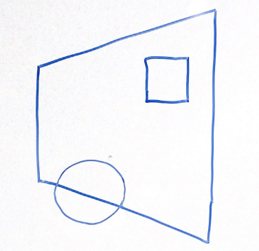
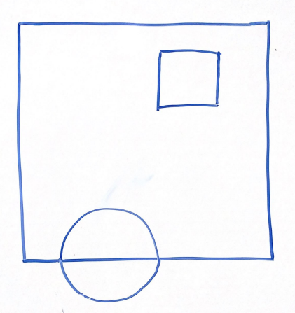
For the above scene in a 2D frustum, which of the following options best represents the same scene after being projected into clip space via a perspective projection? Why?
Think through this one on your own before discussing with your group!
Option 1 | Option 2 |
|---|---|
 |  |
Option 3 | Option 4 |
|---|---|
 |  |
Answer:
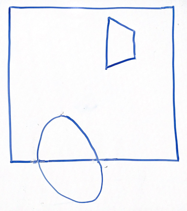
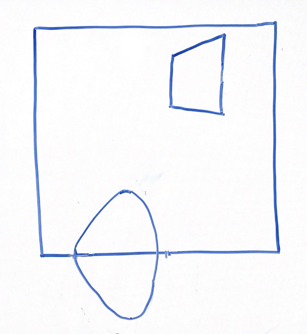
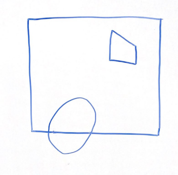
Option 3
Explanation:
Recall that when parallelizing the view frustum, the points closer to the edges will be moved more drastically than those near the midline.
Because of this, option 1 is incorrect, looking at the cube, the edges are equally distorted with respect to the midline.
Option 2 is incorrect because the vertices closer to the right side are stretched incorrectly outwards rather than towards the midline.
Option 4 is incorrect because no transformations occur to the shapes at all.
Scaling & Unhinging
Get together with a group and discuss the scaling and unhinging matrices. Explain why they are useful and how they interact with one another. How do they fit into the Realtime Pipeline?
Answer:
Scaling matrices are used to scale objects within a scene. These matrices modify the size of objects given a far plane and width/height angle, enabling scene elements to have various sizes while maintaining proportions relative to other objects or the camera. Unhinging matrices are critical in correcting the perspective projection. Given a near and far plan these adjust how objects relate to each other in space by aligining them along an axis to accurately simulate perspective effects.
Converting to OpenGL Space
The matrix below is multiplied on the left side of the two matrices above to convert to OpenGL's expected space. What are the x, y, and z limits in OpenGL's clip space and what is this doing to our previous projection to convert it to these limits?
Discuss the different components of this matrix with your group, and be prepared to explain your answers to the TA.
Answer:
Our current perspective transformations map to a space of
Vertex Attributes
Vertex Buffer Format
Using
Don't get too caught up in the details—there may be multiple correct answers here... Have your group draw out the result on the whiteboard!
Answer:
or
or
or
or
or
Explanation:
As long as each attribute is written successively and the permutation of the 3 attributes remains consistent between vertices, any order will do. It is up to you as the programmer to tell your VAO where each attribute is in the VBO and which layout location they reside at.
Vertex Arrays
For each attribute above (position, color, and texture coordinate), please provide the stride and offset (pointer) in bytes using size_of(GLfloat). (Assume GL_FLOAT)
| Stride | Offset | |
|---|---|---|
| Position | ||
| Color | ||
| Texture Coordinates |
Fill in the table above on the whiteboard. Note that your answers here may vary depending on how you answered the previous question
Answer: In the same order as above, this is how you would specify the relative strides and offsets:
| Stride | Offset | |
|---|---|---|
| Position | ||
| Color | ||
| Texture Coordinates |
or
| Stride | Offset | |
|---|---|---|
| Position | ||
| Color | ||
| Texture Coordinates |
or
| Stride | Offset | |
|---|---|---|
| Position | ||
| Color | ||
| Texture Coordinates |
or
| Stride | Offset | |
|---|---|---|
| Position | ||
| Color | ||
| Texture Coordinates |
or
| Stride | Offset | |
|---|---|---|
| Position | ||
| Color | ||
| Texture Coordinates |
or
| Stride | Offset | |
|---|---|---|
| Position | ||
| Color | ||
| Texture Coordinates |
Explanation:
The stride will be
Realtime Pipeline
Conceptual Understanding
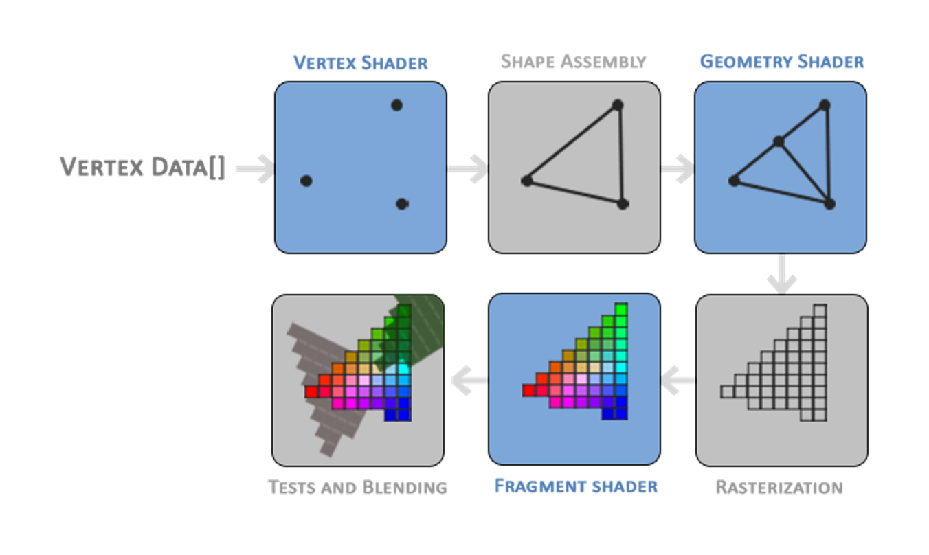
As a group, discuss how the concepts from Labs 8-10 synthesize in the Realtime Pipeline. Looking at the pipeline above, what are vertices, what are fragments and how do vertices and fragments become triangles? More specifically, how do the concepts of Trimeshes, VAOs / VBOs, and Shaders come together to create a final image in the OpenGL pipeline? You may want to refer to the pipeline diagram above to help guide your discussion. You answer shouldn't be too specific, but should demonstrate a high-level understanding of how these concepts interact.
Once your group comes to a consensus, share your answer with the TA.
Answer:
Trimeshes provide a uniform method for defining the structure of 3D models using vertices. These vertices are stored in Vertex Buffer Objects (VBOs), while Vertex Array Objects (VAOs) define the layout and attributes of this data. From here, vertex shaders typically transform the vertices from model space to clip space, and fragment shaders work to determine the final color of each pixel.
Rasterization is the process of determining which pixels should be covered based on the input vertex data. In the OpenGL pipeline, rasterization occurs between the vertex and fragment shaders. In GLSL terminology, the vertex shader output gl_Position is first clipped using the space
Shader Programs
We can perform the same types of computation in both fragment and vertex shader. For this problem, compare the performance considerations associated with applying coordinate transforms in the vertex shader vs. the in fragment shader.
Think on Your Own: If we are drawing 1 triangle which covers exactly 50% of the pixels on an 1280 x 720 image, is it more efficient to compute an operation in the vertex shader or the fragment shader?
Now as a Group: Discuss why this is the case. Exactly how much more efficient does this computation become? In addition, please come up with an example of a computation that must be performed in the fragment shader.
Answer:
This triangle is composed of 3 vertices and covers
Some examples of fragment-only computations include diffuse dot products and specular dot products. Any computation that depends on the position at a given pixel in some way must be done in the fragment shader.
Program Analysis
Erroneous Code
Consider the following initializeGL pseudo-code:
	create VBO
	bind VBO
	fill VBO with data
	unbind VBO
	create VAO
	bind VAO
	set VAO attributes
	unbind VAO
What would be the issue if a student tries calling glDrawArrays to draw their VAO in paintGL?
How could you change this pseudo-code to remove the error?
It may help to refer to lecture if you get stuck here!
Answer:
The VAO currently is not linked to a VBO! The student would see a black screen :(. To fix the issue, moving the unbind VBO call to the end of this pseudocode will do the trick.
Predict the Render
Given a VBO filled with data from an std::vector<GLfloat> of size 18, and VAO attribute code of:
glEnableVertexAttribArray(0);
glEnableVertexAttribArray(1);
glVertexAttribPointer(0, 3, GL_FLOAT, GL_FALSE, 6 * sizeof(GLfloat), nullptr);
glVertexAttribPointer(1, 3, GL_FLOAT, GL_FALSE, 6 * sizeof(GLfloat), reinterpret_cast<void *>(3 * sizeof(GLfloat)));
How many vertices and how many triangles are described in the VBO/VAO pair?
Answer:
Explanation:
In this case we see that each vertex is of size 6 * sizeof(GLfloat). Then given there are 18 elements, there are
If the VAO attribute code was changed to:
glEnableVertexAttribArray(0);
glVertexAttribPointer(0, 3, GL_FLOAT, GL_FALSE, 3 * sizeof(GLfloat), nullptr);
How many vertices and how many triangles are now described in the VBO/VAO pair?
Once you've answered both parts, check your understanding with the TA.
Answer:
Explanation:
In this case we see that each vertex is of size 3 * sizeof(GLfloat). Then given there are 18 elements, there are
Submission
Algo Sections are graded on attendance and participation, so make sure the TAs know you're there!